-
Mail us
sale@tiger-transformer.com -
Phone us
(+86)15155183777 -


Mail us
sale@tiger-transformer.comPhone us
(+86)15155183777
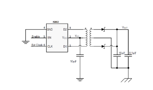
It can be seen from the data sheet that IS802 is a power supply with a push pull architecture, with a total of 6 pins. After reading the schematic diagram, the only thing that is not clear is the Ext clock, so let's take a look at the Ext clock. what's going on.
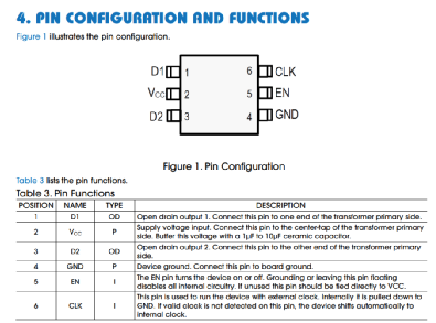
The pin function in the manual says that this pin is internal By default, it is pulled to ground. If there is no external clock input, the internal clock will be used. The description is as follows
But the Pin function does not specify the frequency range of its input, so we continue to look down and find the description in the EC table, as follows, the maximum can reach 2Mhz, and the magnetization of the transformer when it reaches 2Mhzcurrent will be much smaller.

Do not talk about the outside here, FThe function of EXT, we will use the internal frequency to do it below. Its internal frequency is as follows.

The switching frequency is from 300Khz to 550Khz, the switching frequency will affect Volt-second product, if the volt-second product exceeds the limit that the transformer can withstand, the transformer will be saturated. From the manual, we know that the minimum frequency is 300Khz, and the maximum frequency is 500Khz. Usually our input voltage is 3.3V or 5V.
In the case of 5Vpower supply, the maximum volt product is as follows, 8.333V/us, the 2 in formula 1 (IS801 volt-second product calculation formula), comes from the duty of IS802 Than, so Von's time is only half, so /2.
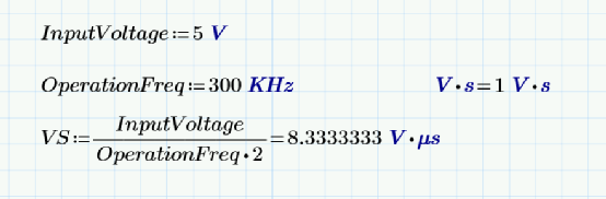
Equation 1: IS802 volt-second product calculation formula
According to the IS802 volt-second product calculation formula, I found the 750313734 transformer on the WE company page, and its volt-second product is larger than our IS802 volt-second product. He doesn't have much problem with volt second product.
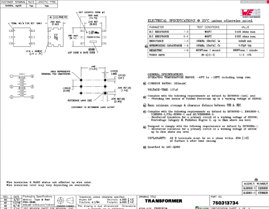
His turn ratio is 1:1.1 and we will Turn ratio into the rough calculation to get the following results, such as formula 2 output voltage rough calculation.
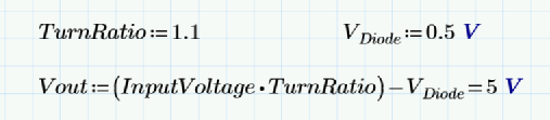
Formula 2: Rough calculation of input voltage
Basically meet the requirements of 5.0V to 5.0V, but in fact there will be some attenuation.
We are looking at the inductance of 750313734 transformer, the inductance of 13 pin is 340uH, then the inductance of two 12 is equal to the inductance of 23 winding At this time, L12+L23~=L13~, then according to the inductance we can get The transformer magnetizing current is 24.51mA.
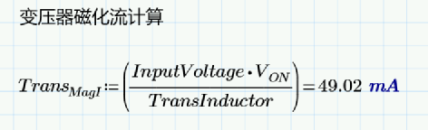
Formula 3: Transformer magnetizing current
< p>Because the magnetizing current rises slowly as shown in the figure below.
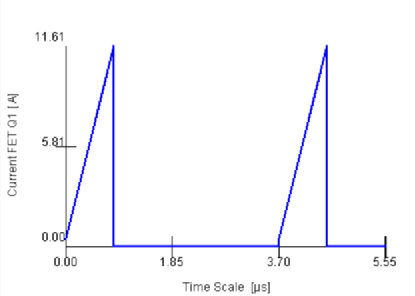
According to the triangle area calculation formula we can get:( Length × width)/2 is his magnetizing current, so 2 in the formula comes from this.
Assume the output we need is 5V 200mA.
Then the current on our D1D2 is as follows
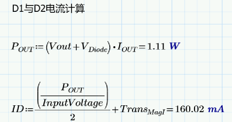
Equation 4: Current on D1D2
Look at the manual in reverse
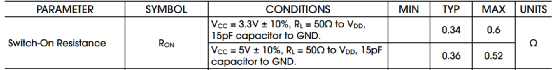
IS802 D1/D2 RDSON
~~Bring the ID into the IS802 power consumption (estimation) The following formula 5
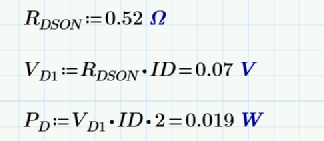
Formula 5: Internal MOS loss estimation
Looking at the power consumption is also good, the power is not too large, the maximum switching current that the internal MOSFET of IS802 can withstand is 500mA (we don’t want to use it up), if we We still have a margin to choose this transformer, and it is safe.
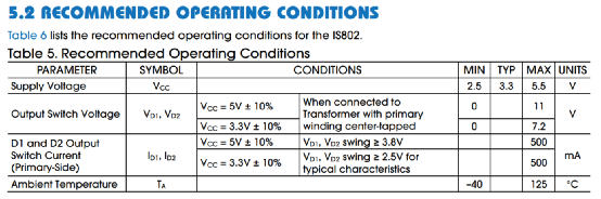
recommendedoperating conditions< /p>
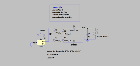
Simulationcircuit
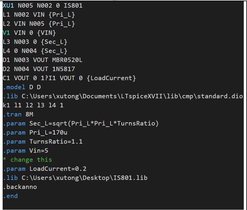
Emulation code
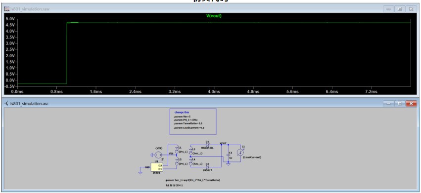
Simulation results