-
Mail us
sale@tiger-transformer.com -
Phone us
(+86)15155183777 -


Mail us
sale@tiger-transformer.comPhone us
(+86)15155183777
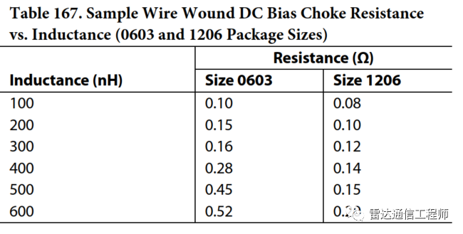
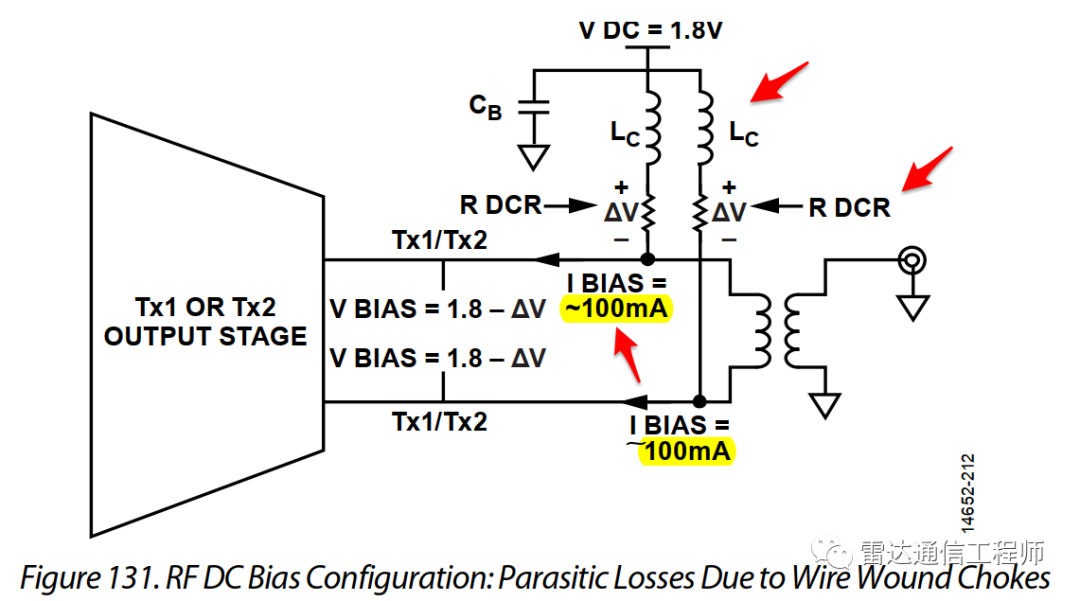
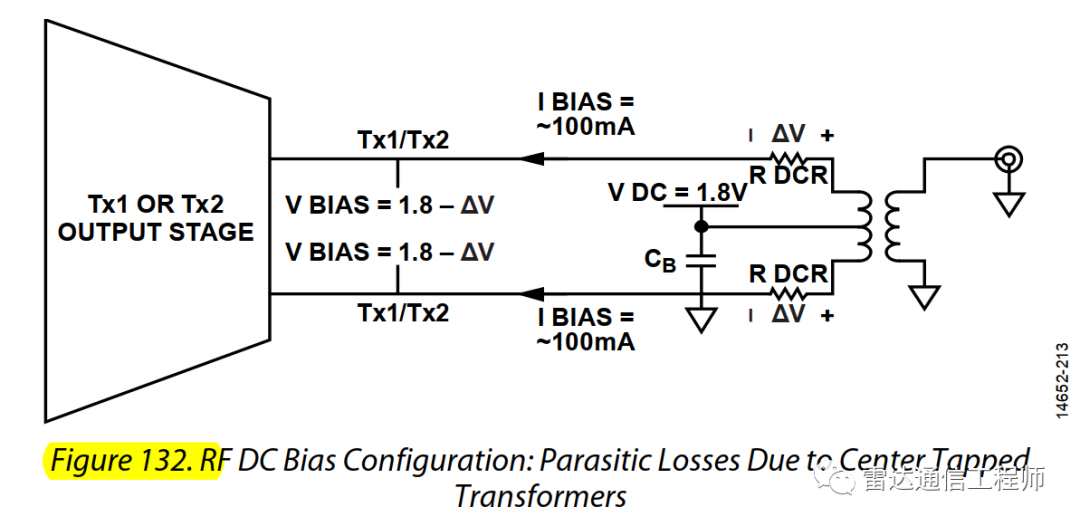
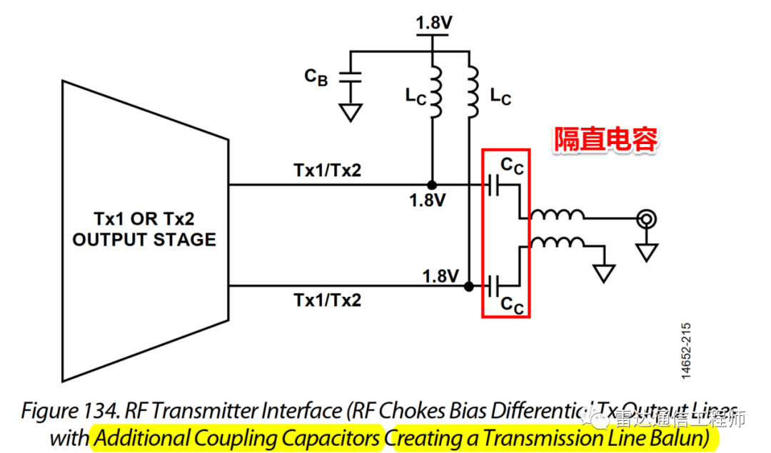
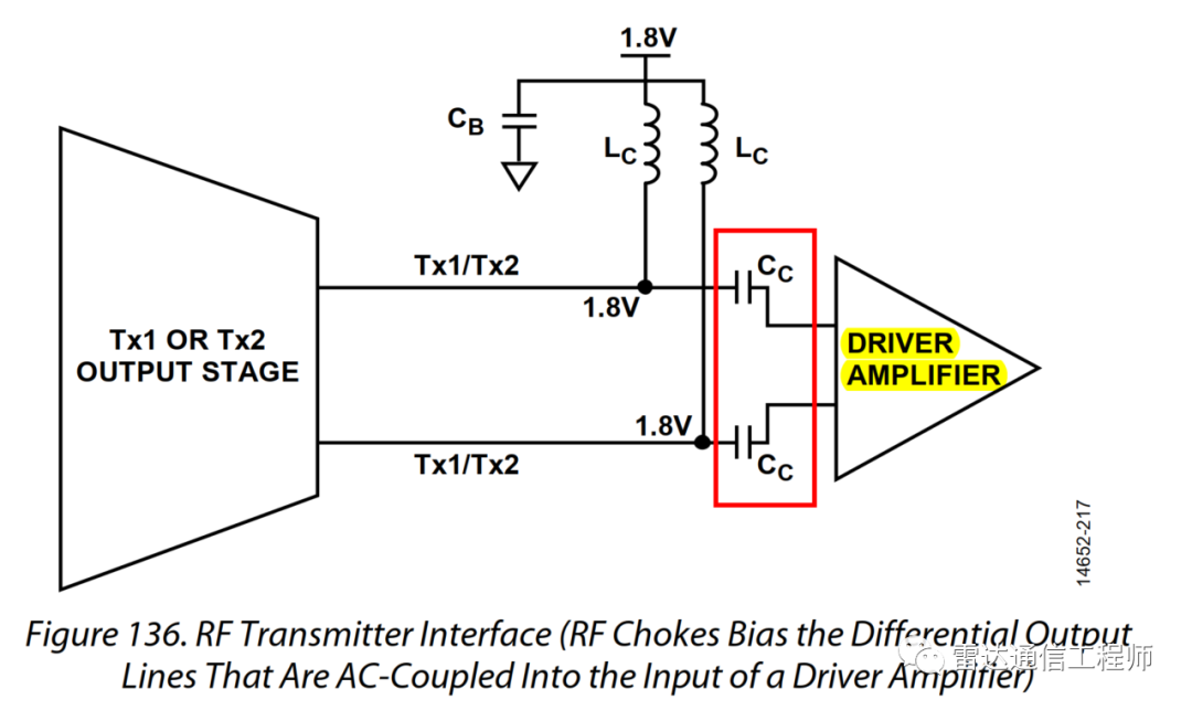
The transmitter port of this series of transceivers is a push-pull differential RF driver. Like the usual RF amplifier, it needs DC feed to provide power, resulting in Two ways of feeding (that is, DC bias), one is to use an external RF choke for feeding, and the other is to use the re-tap of an RF transformer for feeding (use the transformed coil as an RF choke) . In the case of full power output, the maximum sink current of each differential output port can reach 100mA. The parameter selection of the choke coil and RF transformer/balun has an important impact on the RF performance. In order to reduce the DC voltage drop, the increase of the voltage drop will cause the performance of the transmitter to degrade (output P1dB, maximum Pout, etc.), choose a choke inductance (LC) that is high enough relative to the load impedance to avoid reducing the output power (power It will leak to the power supply through the choke coil, so it is easy to interfere with other circuits), but the higher choke inductance LC and the smaller DC resistance are contradictory (under the same volume), and the actual design needs to be balanced.
Practical selection experience: The DC bias current of the transmitter is about 100mA (full-scale power output), here you need to pay attention to the current that the transformer can withstand (the maximum current of many mini wire-wound transformers TC-1-13 30mA (0.25W), while the LTCC transformer current of TDK or mini (NCS1-292+) is 200mA or 3w), you can use a wirewound choke inductor or a balun/transformer center node to feed, but you need to pay attention to choosing a low DC Equivalent resistance devices to minimize the DC voltage drop and ensure the performance of the transmitter; the feed inductance must be large enough relative to the load impedance so as not to cause output power to drop. The recommended DC bias network is to use the center tap of the transformer. The component count and parasitic parameters of this bias network are small.
The unbalance of balun refers to the conversion of single-ended signal When forming a differential signal, the + and - signals of the differential signal are not a pair of ideal differential signals with equal amplitude and opposite polarity, and their amplitude and phase will be somewhat different. The reason is mainly caused by the parasitic capacitance between the primary and secondary coils of the transformer. And the higher the signal frequency, the more significant the difference. The solution can be cascaded with two transformers, which can reduce the imbalance of amplitude and phase. The principle is that after the transformers are cascaded, the parasitic capacitance between the primary and secondary coils of the front and rear stages is connected in series, and the capacitance becomes smaller. . Regarding this, maxim has an application note that specifically talks about using a transformer as the analog front end of the ADC.
The difference between load-pull and small-signal matching:
Load-pull:
Small-signal matching: maximum power based on transfer gain Transmission
The method of using load pull: adjust the differential impedance of the transmitter to achieve the best balance between output power and third-order AC regulation point.
The fundamental wave output power is inversely proportional to the real part of the load impedance
The output third-order intercept point is inversely proportional to the real part of the load impedance
OIP3 is higher for capacitive loads than for inductive loads
optimal transmitter Differential output impedance can be changed
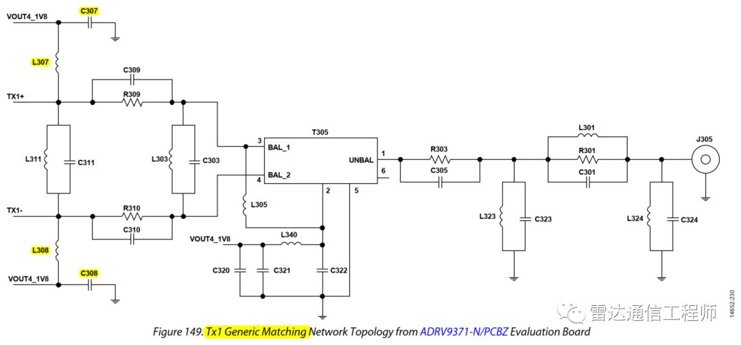
Transmission port matching network
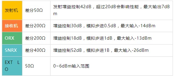
For applications using an external LNA at the receive port, the noise figure of the 9371 is not critical, using an external LNA allows the use of simple impedance Matched topologies for wide RF bandwidth.
Wiring priority: good RF signal JESD204B signal priority is the highest, pay attention to keep a certain degree of isolation between JESD204B differential pairs
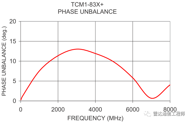
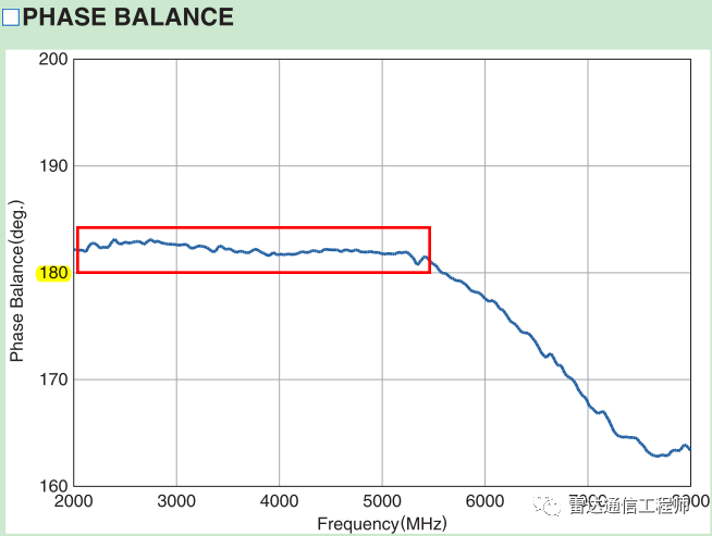
AD9371 can be configured for broadband applications, and broadband applications are required at this time RF balun TCM1-83X+, the balun has a large phase imbalance, while the TDK narrowband LTCC balun phase imbalance is less than 5 degrees (should be less than 5 degrees, the same is true for the front end of the ADC), which meets the requirements
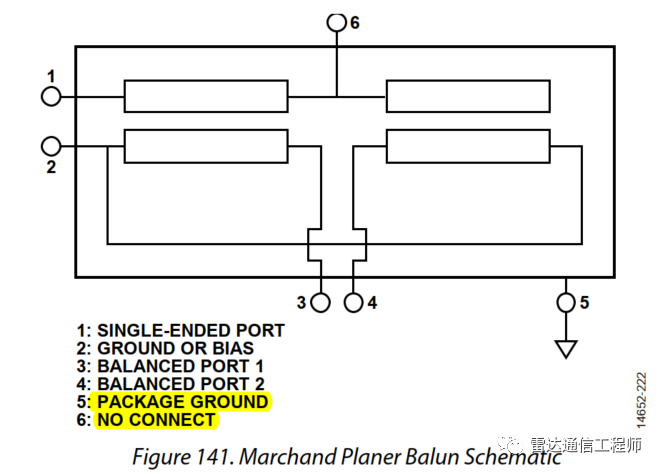
Marchand Planer Balun is very suitable for this application, because this type of balun is generally used The LTCC process is realized, and it can be packaged in 0603 or 0805, which occupies a small volume and is stronger than a wire-wound balun.
When the differential port needs tributary bias, it can feed power from pin 2. If no bias is needed, use DC grounding or AC grounding according to external requirements.
6 feet suspended
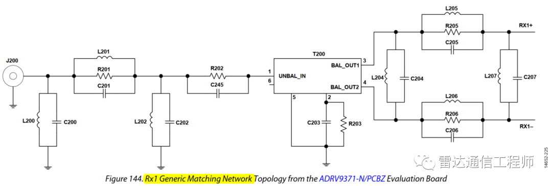
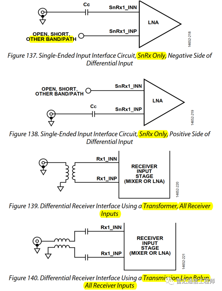
Receiving ports: RX, ORX, and SnRx are all applicable. When designing the schematic diagram, you can change the RLC devices connected in parallel at the same position to only one or multiple parallel connections as shown in the figure, because the actual There is basically only one device (R, L, C) when matching, and multiple devices in the series branch can be overlapped during PCB design, occupying only one device space, and the parallel branch can be placed according to personal preference. Minimize impedance discontinuities and PCB area as much as possible.
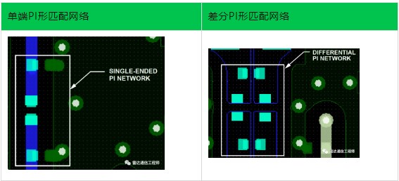
Receiving port matching network