-
Mail us
sale@tiger-transformer.com -
Phone us
(+86)15155183777 -


Mail us
sale@tiger-transformer.comPhone us
(+86)15155183777
1 Overview
At present, the urban rail transit DC traction power supply system uses diode rectifiers, and power can only flow in one direction from the AC grid to the DC traction grid. When the vehicle brakes, excess regenerative braking energy increases the DC grid voltage. The traditional solution is to set up a resistor braking device, but this will cause a great waste of electrical energy and bring about other problems such as temperature rise. Since rail transit vehicles start and brake frequently, the braking energy is considerable. If it can be used rationally, it will produce good economic benefits.
From the earlier application of regenerative energy resistor consumption devices in traction substations to the development of capacitive energy storage, flywheel energy storage technology, and regenerative energy inverter feedback equipment in recent years, regenerative braking energy absorption The technology is continuously developed and improved, and has been applied on rail transit lines at home and abroad. For the four absorption device solutions currently in use, Table 1 gives the characteristics of the four absorption devices:

The regenerative braking inverter device (hereinafter referred to as the inverter device) is an inverter feedback type, and its feedback energy will be used for 400V loads or Back to the 35kV power grid. The inverter device (inverter + resistor) comprehensively determines whether a train on the DC grid is in a regenerative braking state based on the detection signals of each sensor. Once it is confirmed that the train is in a regenerative braking state and needs to absorb energy, the system starts the absorption process. Set the second-level judgment reference value in the control system. When the grid voltage rises to the first-level judgment voltage, the system first puts in the inverter device. The inverter device converts the energy generated when the locomotive brakes into AC380V voltage and automatically tracks it. AC380V bus voltage and supply power to the load, consuming the regenerated energy on the electrical equipment; once the inverter absorbs and cannot consume the energy, it will cause the grid voltage to rise further. When the grid voltage rises to the second level judgment voltage, the resistor chops The device immediately starts working, the resistance absorption device will regenerate the braking energy consumption, and the stable voltage will no longer rise, ensuring that the locomotive can make full and effective use of electric braking. In the DC traction power supply system, the regenerative braking energy absorption device is a subsystem project, and its role is related to the safety of the system.
2 Main loop system of the inverter device
2.1 Overview of the traction power supply system of a certain line in Chongqing
The traction power supply system of a certain line in Chongqing It is mainly divided into two parts: DC traction network and AC distribution network. The main substation sends three-phase 35KV high-voltage AC to each traction station. It is converted into a 1500V DC bus suitable for rail vehicle applications through rectifier transformers and rectifiers. The feeder then sends the DC power to the catenary. The catenary is erected along the vehicle track. A special power supply line, the rail vehicle obtains electric energy through direct contact between its current receiver and the contact grid.
A traction substation is generally equipped with two traction rectifier units. Currently, two rectifier units are operated in parallel to form an equivalent 24-pulse rectification method. Its capacity is designed based on long-term transportation volume. According to the national standard GB/T 10411-2005 "Urban Rail Transit DC Traction Power Supply System", the load capacity of the traction rectifier unit should meet: 100% rated output continuously; 150% rated output 2h; 300 % rated output lmin. The allowable voltage fluctuation range is 1000V ~ 1800V. The running rails form part of the traction power supply circuit. The return line leads the track return to the traction substation.
The AC distribution network mainly provides infrastructure such as lighting, ventilation, drainage, and elevators in the station.
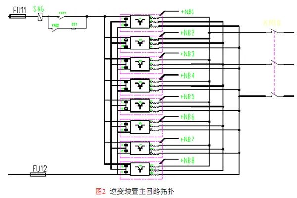
2.2 Main circuit topology of the inverter device
The main circuit topology of the inverter device is divided into four parts, such as DC contactor components, inverter unit, output reactor, and AC contactor components. As shown in Figure 2;
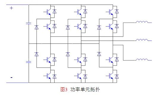
2.3 Power unit topology
The unit of the inverter device adopts a three-level structure circuit. The main circuit of the unit is shown in Figure 3.
3 Principle and function of inverter device
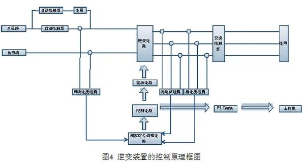
3.1 Working principle
After receiving the "start" given signal, the inverter device operates the DC contact through the control loop and AC contactor, and sends a start-up completion confirmation signal. After the main control device detects the start-up confirmation signal, it will give a high-level "start" signal according to the level of the bus voltage at this time to perform energy feedback; the low level will instantly shut down the inverter equipment and be in an energy feedback waiting state. During the working process of the inverter equipment, it always receives and promptly responds to the working status signals of the contactors and each unit in the equipment. Figure 4 is the control principle block diagram of the device.
3.2 Main functions
(1) The inverter device mainly realizes functions such as automatic grid connection, inverter absorption and inverter current adjustment according to changes in bus voltage.
(2) The inverter device is equipped with over-voltage, over-current, over-temperature and short-circuit protection functions. When a certain inverter unit fails, the whole machine can still operate at a derated level without affecting the normal operation of the whole machine. The working status of the whole machine is transmitted to the host computer and waits for its control instructions.
(3) Automated data collection function, the microcomputer control system consists of a PLC control system and a 16-bit DSP system. Collect DC and AC power grid data in real time, automatically adjust the output current of the inverter unit according to changes in the DC bus voltage, and invert the AC power into the same frequency and phase as the grid voltage and send it back to the grid.
(4) The microcomputer control system uses a standard data communication port to connect to the substation comprehensive automation system. The physical interface adopts RS485 interface with a baud rate of 19.2kbps. The communication protocol adopts MODBUS-RTU, which is currently used internationally, and has good versatility and openness.
4 Operational Benefit Analysis
According to the data measured by the owner's watt-hour meter, the inverter device of a line in Chongqing has obvious energy saving effect. The specific data are shown in Table 2;
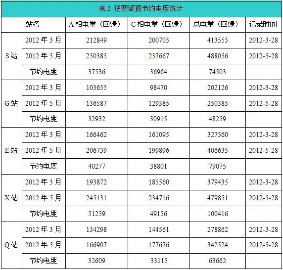
According to the analysis of operating data, the inverter device installed at a subway station feeds back more than 1,000 kilowatt hours of electric energy on average every day. With reference to the industrial electricity price of 1 yuan/kwh, it saves more than 1,000 yuan in operating costs per day and 360,000 yuan in annual costs. Yu Yuan. At the same time, the demand for ventilation and heat dissipation inside the tunnel is reduced. If there is no inverter device, this part of the energy will be considered to be lost, and the operating cost will also increase accordingly. Therefore, the economic benefits of equipment operation are significant.
5 Conclusion
Rail transit has the technical advantages of large capacity, fast speed, safety, reliability, punctuality and comfort and is gradually becoming a means of transportation in major cities. The social and economic attributes of urban rail transit have made it the focus of urban transportation development strategy, and it is also regarded as the backbone of the urban transportation system. At the same time, the country began to pay attention to the localization of products. Under the guidance of the national equipment localization policy, a number of rail transit equipment manufacturers and scientific research institutes gradually grew, advancing the process of product localization.