-
Mail us
sale@tiger-transformer.com -
Phone us
(+86)15155183777 -


Mail us
sale@tiger-transformer.comPhone us
(+86)15155183777
The zero deflection angle of the motor position sensor (that is, the zero deflection angle or initial angle of the resolver) is crucial to the accuracy of the motor output torque. For the new energy 150KW drive motor, when the resolver zero deflection angle has an electrical angle offset of +/-2, it will cause an error of about +/-3Nm in the output torque of the motor at low speed without field weakening, and at high speed The error of about +/-8Nm in the field weakening area.
The following will introduce the following points: the zero deflection angle of the motor position sensor and its calibration, that is, the zero deflection angle of the resolver and its calibration:
What is the resolver zero deflection angle?
Why does every motor need to calibrate the zero deflection angle of the resolver?
How to calibrate the zero deflection angle of the resolver?
1. Resolver sensor zero deflection angle
Taking a three-phase permanent magnet synchronous motor as an example, according to the Vector control technology can determine each coordinate system.
1). Stationary coordinate system ABC: The three phases of the stator winding are symmetrical, and the axes differ by 120 degrees. Taking the stator UVW three-phase as a reference, determine the static coordinate system ABC, as shown in Figure 1 shown.
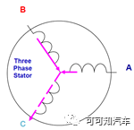
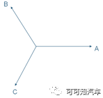
Figure 1. Stationary coordinate system ABC
2). Stationary coordinate system αβ: α axis coincides with A axis, 90 degrees ahead of the α-axis is the β-axis, as shown in Figure 2.
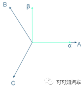
Figure 2. Static coordinate system αβ
3). Rotor synchronous rotation coordinate system dq: The central axis of the N-pole that produces the magnetic field generated by the magnetic poles of the motor rotor is defined as the direct axis d-axis; and the position 90 degrees ahead of the direct axis is defined as the quadrature axis q-axis . The dq axis rotates at the synchronous angular velocity ω of the rotor, assuming that the counterclockwise direction of the rotor is positive, as shown in Figure 3
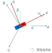
Figure 3. Rotor synchronous rotation coordinate system dq
4). Resolver zero position: refers to the resolver The zero position of the position sensor, when the induced voltage in the sinusoidal output winding of the resolver is the smallest, the rotor position is the electrical zero position, and the output voltage is the zero position voltage. Assuming that when the dq-axis coordinate system rotates to the position d', q', the angle actually measured by the resolver sensor is zero, then define the position of the d' axis as the zero position of the resolver, as shown in Figure 4, the zero position of the resolver is fixed.
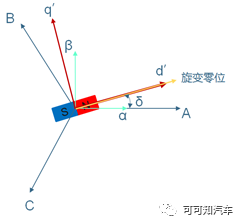
Figure 4. The D axis coincides with the zero position of the resolver Schematic diagram
5). Angle θ actually measured by the resolver sensor: In Figure 4, the d-axis coincides with the zero position of the resolver. When the rotor continues to rotate counterclockwise, the resolver The zero position and the d-axis will form an included angle θ, as shown in Figure 5, the included angle θ is the angle actually measured and output by the resolver sensor. When the rotor rotates until the d-axis coincides with the zero position, the output angle θ=0 degrees actually measured by the resolver sensor is shown in Figure 4.
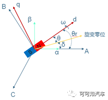
Figure 5. Schematic diagram of rotor position and angle
6). Resolver sensor zero deflection angle δ: is the angle between the resolver zero position and the A-axis, which is the angle that the motor needs to calibrate. As shown in Figure 4.
7).Motor rotor position angle θr **: ** is the angle between d-axis and A-axis , as shown in Figure 5. It can be seen that: θr =θ+δ.
For the permanent magnet synchronous motors for electric drive, most of them use four pairs of poles, so the above-mentioned angles need to be converted into corresponding electrical angles.
2. Why each motor needs to be calibrated for the zero deflection angle of the resolver
According to the vector control of the permanent magnet synchronous motor, for the motor output To maximize the torque, the electromagnetic field generated by the stator winding is always orthogonal to the permanent magnetic field of the rotor, so it is necessary to accurately obtain the rotor position angle θr, that is, accurately obtain θ and δ.
The accuracy of the actual measurement angle θ of the resolver sensor depends on factors such as the electrical error of the resolver sensor, the output orthogonal axis error, the decoding calculation error, and the manufacturing accuracy of the resolver sensor itself. consider.
For the accuracy of the resolver sensor’s zero deflection angle δ, ideally, the development and design stage of the motor can ensure that the resolver’s transmission zero position coincides with the A axis, that is, the resolver’s zero deflection angle δ= 0. However, due to the fact that there are processing deviations and installation deviations in the motor production process, the actual positioning of the resolver sensor is inconsistent, so that the deflection angle of the resolver sensor of each motor is inconsistent. Therefore, each motor needs to be calibrated for the zero deflection angle of the resolver sensor during offline inspection.
3. Calibration of the zero deflection angle of the resolver
**3.1 **Calibration method one
When a certain three-phase current is given, the UVW three-phase synthetic current is always points to the A axis, that is, the U phase. At this time, the induced magnetic field generated by the current is interacts with the magnetic field of the rotor permanent magnet, so that the d axis (that is, the rotor The N pole) coincides with the A phase. At this time, the actual measurement angle of the resolver sensor can be read, as shown in Figure 6, and the zero deflection angle of the resolver sensor can be calculated: δ=360-θ.
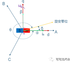
Figure 6. Schematic diagram of stator current is pointing to axis A< /p>
According to the above theory, in engineering applications, two methods of manual calibration and automatic calibration can be realized.
Manual calibration: Using a low-voltage DC power supply and a resolver sensor device, connect the U phase of the motor winding to the positive pole, the V phase and W phase to the negative pole, and connect the When the power is turned on, the rotor of the motor rotates to a certain position. At this time, the resolution device of the resolver sensor reads the angle. If 90 ^0^ <θ<360 ^0^ , then the zero deflection angle of the resolver sensor: δ=360-θ; if θ<=90 ^0^ , then the zero deflection angle of the resolver sensor: δ=θ.
Automatic calibration: The manual calibration process mentioned above is built into the motor controller, the motor is unloaded, and the DC voltage of the motor controller is given to control the U-phase electric current as For a certain value, the V-phase and W-phase currents are corresponding negative values, then the motor will move the rotor to a certain fixed position, the A-axis and the D-axis coincide, and the angle read by the resolver is the zero deflection angle of the resolver.
Due to the existence of bearing friction and the effect of inertia, the above calibration process will lead to a deviation between the zero position of the resolver and the coincidence of the A axis. In addition, due to mechanical tolerances, for each electrical cycle of a mechanical rotation Measured angular offset may vary. Therefore, consideration must be given to determining the resolver zero deflection angle by repeating the calibration for each electrical cycle and calculating the average angle.
Similarly, the zero deflection angle of the resolver can also be calibrated by directly giving the β-axis voltage vector in the voltage loop through the motor controller.
This calibration method: the method is simple and easy to realize automatic calibration. The calibrated resolver has a higher precision of the zero position deflection angle.
**3.2 **Calibration method 2
PSM motor torque equation:
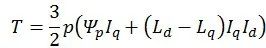
When the resolver zero position deflection angle is correct, and the resolver sampling is correct, when the Id and Iq are given, the motor The output torque is T; when Id and -Iq are given, the torque output by the motor is -T. Under a given current, only when the zero deflection angle of the resolver is correct, the torque T output by the motor is maximum.
The above theory can use the controller of the motor itself and the dynamic test bench to determine the calibration of the zero deflection angle of the resolver:
Step1: Supply DC rated voltage to the motor control, The motor is controlled in torque mode; at the same time, the motor to be marked is dragged to a certain speed by the measuring and controlling machine, such as 3000rpm, but not in the field-weakening speed zone, and the measuring and controlling machine records the output torque of the motor;
Step2: Through the motor control Manually set the d-axis current Id;
Step3: Calibrate and modify the zero deflection angle of the resolver, recorded as
Step4: Manually set the q-axis current Iq;
p>Step5: Read the motor output torque, denoted as T+;
Step6: Manually set the q-axis current -Iq;
Step7: Read the motor output torque again, denoted as T-;
Step8: Repeat the above steps from step3 to step7 until T+ and T- are positive and negative symmetrical, and when the absolute values are equal, the resolver zero deflection angle is calibrated successfully.
This calibration method: basically relies on trial and error, low efficiency, and it is not easy to realize automatic calibration; it can be used to verify and optimize the accuracy of the resolver's zero deflection angle.
**3.3 **Calibration method three
Adopt a position sensorless strategy to calculate the rotor position angle of the motor, and then subtract the actual measurement of the resolver , the zero deflection angle of the resolver can be obtained. There are various strategies for estimating the rotor position angle without a position sensor, one of which is shown in Figure 7.
This calibration method: without the help of a measurement and control machine, the accuracy of the resolver's zero deflection angle depends entirely on the sensorless estimation strategy.
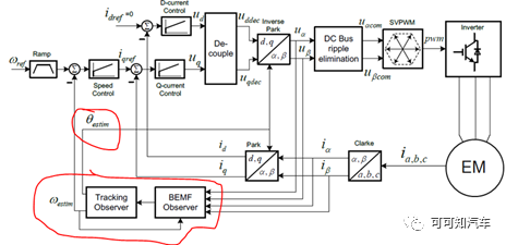
Figure 7. Sensor-less rotor position angle estimation Principle block diagram
**3.4 **Calibration method four
Using the back electromotive force waveform to correctly reflect the motor rotor position angle waveform. In the process of calibration, it is necessary to use the measuring and controlling machine to drag the motor to be calibrated to a certain speed, and then the motor will generate a corresponding counter electromotive force. First, a power analyzer can be connected externally to detect the waveform of the back electromotive force, thereby deriving the waveform of the rotor position angle of the motor, as shown in Figure 8. Second, the motor controller can enter the active short-circuit working state through the software control algorithm, that is, the three-phase IGBT enters "the upper half bridge is fully open/the lower half bridge is fully closed" or "the upper half bridge is fully closed/the lower half bridge is fully open". In the working state of ", the motor will heat up, and the three-phase current waveform generated at this time can be solved to calculate the rotor position angle and the zero position deflection angle of the resolver.
This calibration method: need to use the measurement and control machine to realize automatic calibration. The calibrated resolver zero position deflection angle accuracy is very high.
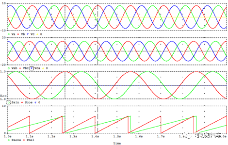
Figure 8. Schematic diagram of back electromotive force and its position angle waveform
The above are the four commonly mentioned calibration methods for the zero deflection angle of the resolver. Of course, there are many other methods to calibrate the zero deflection angle of the resolver. The theory is derived from the motor control models and algorithms. Finally, allow me to say one more nonsense: if you are familiar with the control model or algorithm of the motor, it will be easier to understand each calibration method or strategy.