-
Mail us
sale@tiger-transformer.com -
Phone us
(+86)15155183777 -


Mail us
sale@tiger-transformer.comPhone us
(+86)15155183777
The test of the RF transformer can be treated as a balun, and the test can be completed by combining the port extension (offset) and virtual differential mode of Yanet.
Although it can be used as a balun, the RF transformer is still quite special because it has an impedance conversion ratio, such as 1:1, 1:2, 1:4, etc., and the single-ended impedance is not necessarily the commonly used 50 Ohm system impedance. So what is the differential impedance and common mode impedance of the RF transformer?
Figure 1 shows a typical schematic diagram of an RF transformer. The PRI end of the primary coil is single-ended, and the SEC end of the secondary coil is a balanced end. Assuming that the input impedance (single-ended impedance) is 50 Ohm, and the impedance conversion ratio is 1:2, the differential impedance is the product of the input impedance and the impedance ratio, which is 100 Ohm, and a quarter of the common-mode impedance differential impedance, which is 25 Ohm .
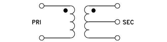
Figure 1. Typical RF Transformer Schematic
This is a balun often used in RF applications, single-ended 50 Ohm/differential 100 Ohm. The impedance ratio of RF transformers is various, and the single-ended impedance is not necessarily 50 Ohm. Table 1 gives several examples of different impedance transformation ratios and input impedances for easy understanding.
Table 1. Differential mode and common mode impedances corresponding to various impedance ratios and input impedance
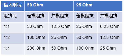
The reason for paying attention to these parameters is that they need to be set separately in the reference impedance setting of the vector network port.
After introducing the calculation method of differential impedance and common mode impedance, let's talk about Yawang's port extension technology - Offset. The Offset function has a certain premise, that is, it is considered that the network to be compensated (such as PCB traces) is ideal: (1) non-dispersive; (2) matching on the calibration reference plane; (3) reciprocity.
The Offset function calculates the transmission characteristics of the network to be compensated according to the reflection test, so that the test reference surface extends to the pin of the DUT. Because the application is based on some ideal conditions, it has limitations, and the accuracy is also limited.
In addition to using the Offset function, there is also a calibration method with higher precision——self-made TRL calibration kit, which can directly calibrate the test reference surface to the pin of the DUT. Figure 2 shows a schematic diagram of self-made TRL calibration parts, including Through, Reflect (generally designed as an open circuit), Line calibration parts and test fixtures. The reason why the TRL calibration part is made together with the test fixture is because it can avoid the influence of factors such as processing errors and dielectric substrate uniformity on the test to the greatest extent.
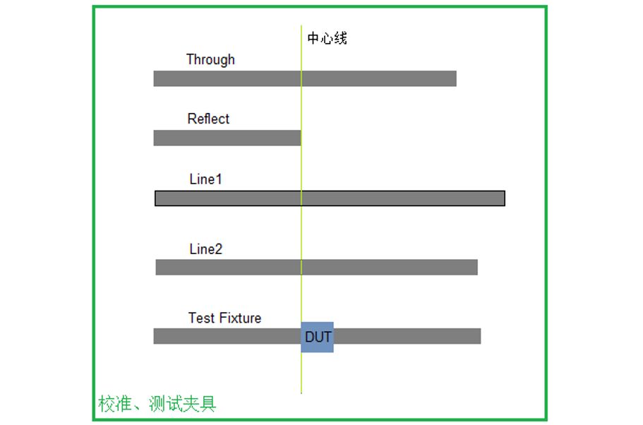
Figure 2. Schematic diagram of self-made TRL calibration parts
About TRL calibration, there will be a special introduction later, here is only a brief explanation. The TRL calibration method is very suitable for the non-coaxial DUT test of SMT surface mount. The test of this kind of device needs the help of test fixture or evaluation test board, and TRL can directly calibrate the test reference surface to the pin, so how to do it? up to this point?
Whether it can be calibrated to the pin is related to the size design of the TRL calibration part and the parameters of the calibration part set in the vector network. For example, the length of Through is designed to be the sum of the lengths of the PCB traces on both sides of the DUT in the test fixture. Here, it is assumed that the two traces have the same length; the length of Reflect is designed to be half the length of Through.
Setting the electrical length of Through to 0 in the vector grid is equivalent to selecting the pin as the calibration reference plane. The parameters of Reflect do not need to be set, TRL calibration does not need to know its parameters, as long as the two ports of Yanet are connected to the same Reflect calibration part during calibration. Generally, Reflect is designed as an open circuit.
There is an applicable calibration frequency range for the TRL calibration kit, which depends on the difference between the electrical lengths of Line and Through. This calibration method requires that the difference between the electrical lengths of Line and Through cannot be an integer multiple of the half-wavelength of the center frequency, otherwise there will be bad values in the calibration data. From the perspective of phase, at the center frequency, it is generally recommended that the phase difference between the two be between 20° and 160°. From this, it can be deduced that the applicable frequency range is:
**f_start=1/18 ∗ c/l, f_stop=4/9 ∗ c/l **
where , c is the phase velocity of the signal in the substrate, and l is the difference between the electrical lengths of Line and Through.
In order to expand the applicable frequency range, multiple Lines can also be used, for example, two Lines are used in Figure 2. Even introduce Match calibration parts to complete the extension to lower frequencies.