-
Mail us
sale@tiger-transformer.com -
Phone us
(+86)15155183777 -


Mail us
sale@tiger-transformer.comPhone us
(+86)15155183777
Electrical fast burst There are three reasons for the impact on equipment.
( 1) The power supply of the device is directly conducted through the power supply line, resulting in excessive noise voltage on the power line of the circuit. When the interference source is injected into the live wire or the neutral wire alone, there is a differential mode interference between the live wire and the neutral wire, and this differential mode voltage will appear at the DC output of the power supply; When the interference is injected into the neutral line, only the common-mode voltage exists. Since the input of most power supplies is balanced (regardless of the input of the transformer or the input of the rectifier bridge), the actual common-mode interference turns into a poor The modulus voltage has very few components and has little effect on the output of the power supply.
(2) Interference energy radiates to the space during the conduction process on the power line, and the energy is induced to the adjacent signal cable, causing interference to the circuit connected by the signal cable (If this happens, it will often cause the test to fail when injecting the test pulse directly into the signal cable).
(3) The secondary radiation energy generated when the interference pulse signal propagates on the cable (including signal cable and power cable) is induced into the circuit and interferes with the circuit.
1. Reasons for group pulse failure
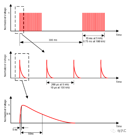
For testing the immunity of equipment, the electrical fast pulse group (group pulse) test is of typical significance, because the electrical fast pulse test The rising edge of the waveform is very steep, so it contains a lot of high-frequency harmonic components, which can test the immunity of the circuit in a wide frequency range. In addition, since the test pulse is a pulse train that lasts for a period of time, it has a cumulative effect on the interference of the circuit. In order to resist transient interference, most circuits install an integrating circuit at the input. This circuit has a good effect on a single pulse. Inhibition, but it cannot be effectively inhibited for a series of pulses.
Rectification measures for the reasons for group pulse failure
1) Measures for power lines
(1) Metal chassis. The main solution to the power line interference problem is to install a power line filter at the power line entry to prevent interference from entering the equipment. From the interference injection method shown in the figure, it can be seen that the voltage injected into the power line is a common-mode voltage, and the filter must be able to suppress this common-mode voltage in order to make the equipment under test pass the test smoothly. At present, many finished power filters on the market are mainly designed for electrical fast pulse tests, and designers can directly select them according to the characteristics of products. The following is a method of suppressing electrical fast pulses on the power line with a filter.
(2) The equipment chassis is non-metallic. If the equipment uses a non-metallic chassis, a metal plate must be added at the bottom of the chassis to ground the common mode filter capacitor in the filter. As shown in the figure, the common mode interference current path at this time forms a path through the distributed capacitance between the metal plate and the ground layer. If the size of the device is small, it means that the size of the metal plate is also small. At this time, the capacitance between the metal plate and the ground layer is small, which cannot play a good bypass role. Therefore, the characteristics of the inductor are very important for the equipment to pass the test smoothly. Various measures need to be taken to improve the high-frequency characteristics of the inductor, and multiple inductors can be connected in series if necessary.
2) Measures for signal lines
(1) Signal cable shielding. It can be seen from the test method that the interference pulse coupling into the signal cable is capacitive coupling. The way to eliminate capacitive coupling is to shield the cable and ground it. Therefore, the condition for using cable shielding to solve electrical fast pulse interference is that the cable shielding layer can be reliably connected to the reference ground layer in the test. If the shell of the equipment is For equipment that is metal and grounded, this condition is easy to meet; when the shell of the equipment is metal but not grounded, the shielded cable can only suppress the high-frequency components in the electrical fast pulse, which is through the connection between the metal shell and the ground. The distributed capacitance between them is grounded; if the chassis is a non-metallic chassis, the method of cable shielding has no effect.
(2) Install a common mode choke coil on the signal cable. The common mode choke coil is actually a low-pass filter. According to the suppression effect of the low-pass filter on pulse interference, it can only be effective when the inductance is large enough. However, when the inductance of the choke coil is large (usually the number of turns is large), the distributed capacitance is also large, and the high-frequency suppression effect of the choke coil is reduced. The electrical fast pulse waveform contains a large number of high-frequency components. Therefore, in actual use, it is necessary to pay attention to adjusting the number of turns of the choke coil, and if necessary, use two choke coils with different turns in series to meet the requirements of high frequency and low frequency.
(3) Use a twisted pair as the signal cable of the device, and add a ferrite magnetic ring at the interface of the device signal line (that is, the end close to the device), and connect the signal line to the magnetic ring Winding up 2~3 times is good for the equipment whose anti-interference ability is not too weak.
(4) Install a common-mode filter capacitor on the signal cable. This filtering method has better results than choke coils, but requires a metal chassis as the ground for the filter capacitor. In addition, this method will attenuate the differential mode signal to a certain extent, so you need to pay attention when using it.
(5) Partial shielding of sensitive circuits. When the chassis of the equipment is a non-metallic chassis, or the shielding and filtering measures of the cable are not easy to implement, the interference will be directly coupled into the circuit. At this time, the sensitive circuit can only be partially shielded, and the shielding body should be a complete hexahedron.
Electromagnetic Compatibility Tips for rectification:
1) Differential mode interference and common mode interference
1.1 Differential mode interference: exists between the LN lines, the current enters from L, flows through the anode of the rectifier diode, and then flows through the load , through the hot ground, to the rectifier diode, and then back to N. In this path, there are high-power devices with high-speed switching and diodes with extremely short reverse recovery times. These devices generate high Any frequency interference will flow through the entire circuit and be detected by the receiver, resulting in conduction exceeding the standard.
1.2 Common mode interference: Common mode interference is because there is a parasitic capacitance between the ground and the equipment cable, and high-frequency interference noise will pass through the parasitic capacitance, and between the ground and the cable Common-mode currents are generated between them, resulting in common-mode interference.
The picture below shows the conduction FALL data caused by differential mode interference. The front end of the test data exceeds the standard, which is caused by differential mode interference:
The following picture shows the switching power supply EMI principle part:
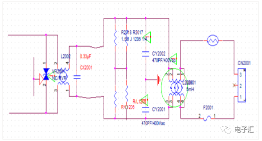
In the figure, CX2001 is Safety regulation film capacitor (when the capacitor is broken down or damaged, it will appear as an open circuit) it spans between the L line and the N line, when the current between LN flows through the load, it will be High-frequency clutter is brought into the loop. At this time, the function of the X capacitor is to form a loop between the load and the X capacitor, so that the high-frequency shunt will be consumed in this loop without entering the mains, that is, the short-circuit AC through the capacitor will prevent the interference from being connected to the loop. external.
Rectification countermeasures for differential mode interference:
1. Increase the capacitance of X capacitor
2. Increase the inductance of common mode inductor, and use its leakage inductance to suppress differential mode noise (because there are several winding methods for common mode inductors, double wire parallel winding or double wire winding The wires are wound separately. Regardless of the winding method, due to the loose winding and the difference in wire length, there will definitely be magnetic flux leakage, that is, the magnetic field lines generated by one coil cannot completely pass through the other coil, which makes there is a gap between the LN wires. Induced electromotive force, which is equivalent to connecting an inductor in series between LN)
The following figure shows the common mode interference test FALL data:
The parasitic capacitance between the power cable and the ground makes common mode interference With a loop, the interference noise flows through the capacitor to the ground, forming a common-mode interference current between the LISN-cable-parasitic capacitance-ground, which is detected by the receiver, resulting in excessive conduction (this can also explain why some motherboards During the conduction test, if the ground wire is not grounded, it will exceed the standard.
In the USB mode, when the ground is not grounded, the current loop can only pass through the L-diode-load-hot ground -Diode-N, the common mode current cannot return to LISN, the noise detected by LISN is small, and when the cold ground of the motherboard is directly connected to the ground, there is a loop between the cable and the ground, At this time, if the common mode noise is not absorbed by the front-end LC filter circuit, it will lead to excessive conduction)
Rectification measures for common mode interference:
1. Increase the common mode inductance
2. Adjust the LC filter on L-GND and N-GND to filter out common mode noise
3. The motherboard should be grounded as much as possible to reduce the impedance to the ground, thereby reducing the parasitic capacitance between the cable and the ground.
2) The EMC disturbance sources of the product include:
1. The switching circuit of the switching power supply of the equipment: the main frequency of the disturbance source Ten kHz to more than a hundred kHz, and the higher harmonics can be extended to tens of MHz.
2. The rectification circuit of the DC power supply of the equipment: the frequency upper limit of the power frequency linear power supply rectification noise frequency can be extended to hundreds of kHz; the switching power supply high frequency rectification noise frequency upper limit can be extended to dozens of MHz.
3. The brush noise of the DC motor of electric equipment: the upper limit of the noise frequency can be extended to hundreds of MHz.
4. Operating noise of AC motors in electric equipment: high-order harmonics can extend to dozens of MHz.
5. Disturbance emission of the frequency conversion speed regulation circuit: the frequency of the disturbance source of the switch speed regulation circuit ranges from tens of kHz to tens of MHz.
6. Switching noise of equipment operating state switching: The upper limit of the frequency of noise generated by mechanical or electronic switching action can extend to hundreds of MHz.
7. Intelligent control equipment crystal oscillator and digital circuit Electromagnetic disturbance: The main frequency of the disturbance source is dozens of kHz to dozens of MHz, and the high-order harmonic Waves can extend to hundreds of MHz.
8. Microwave leakage of microwave equipment: the main frequency of the disturbance source is GHz.
9. Electromagnetic induction electromagnetic disturbance emission of heating equipment: The main frequency of the disturbance source is tens of kHz, and the higher harmonics can be extended to tens of MHz.
10. The local oscillator and its harmonics of the high-frequency tuning circuit of TV electro-acoustic receiving equipment: the main frequency of the disturbance source is tens of MHz to hundreds of MHz, and the higher harmonics can extend to several GHz.
11. Digital processing circuits of information technology equipment and various automatic control equipment: the main frequency of the disturbance source is tens of MHz to hundreds of MHz (the main frequency can reach several GHz through internal frequency multiplication), and the high-order Harmonics can be extended to more than ten GHz.