-
Mail us
sale@tiger-transformer.com -
Phone us
(+86)15155183777 -


Mail us
sale@tiger-transformer.comPhone us
(+86)15155183777
6.1. Several basic laws
6.1.1 Biot-Savart law
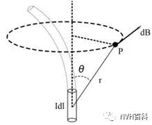
Figure 6.1 Biot Savart's Law
Current
CurrentB generated by u>element Idl at a certain point P in space is proportional to the size of the current element Idl, and is proportional to the current element Idl to P The position vector of a point is proportional to the sine of the angle between the current element Idl, and inversely proportional to the square of the distance from the current element Idl to point P.

It describes the current element at any point P in vacuum Quantitative calculation of the excited magnetic field, of course, the total magnetic field at point P should be the vector superposition of the magnetic induction intensity dB of all current elements at point P.
6.1.2. Ampere's loop theorem
The Biot-Savart law provides a method for calculating the magnetic induction B from the current, so The law can be launched:

Figure 6.2 Ampere's loop theorem
That is, Ampere's loop theorem: in a vacuum with a constant magnetic field , the line integral of the magnetic field strength vector H along any closed path is equal to the algebraic sum of the currents surrounded by the closed path.
When there is a magnetic medium, the Ampere loop theorem still applies, but the value of the magnetic field strength H should be: H=B/μ0-M.
6.1.3. Full current law
The full current law is the generalization of the Ampere loop theorem by Maxwell. The magnetic pressure is equal to the algebraic sum of all types of currents passing through the plane surrounded by this closed loop.

Ampere's loop theorem does not apply to non-constant currents, For example, take a closed curved surface between the two plates of capacitor, since the curved surface does not surround the conduction current (the current generated by the movement of charges in the medium), the right side of the Ampere loop theorem is zero; if there is a conduction current Take the loop at the place, the current sum is not zero, which leads to a contradiction when using the Ampere loop theorem;
Maxwell put forward the hypothesis: the changing electric field can excite the magnetic field around it, and the rate of change of the electric field is defined It is the displacement current, the displacement current is not the current for the directional movement of the charge, but the changing magnetic field it can cause is equivalent to the changing magnetic field caused by the conduction current.
Full current means that the current passing through a certain section of space should include the sum of conduction current and displacement current; full current is continuous and forms a closed loop in space. There is a conduction current in the wire, and a displacement current in the capacitor, that is, where the conduction current is interrupted, there is a displacement current to continue. At this time, the Ampere loop theorem is established, so the full current law is the Ampere loop It is a complement to the theorem, and it is also one of the theoretical foundations for Maxwell's prediction of the existence of electromagnetic waves.
6.2 Magnetic circuit
6.2.1 Definition and composition of magnetic circuit
Magnetic flux passes through The path of the magnetic medium is called the magnetic circuit;
Similar to the circuit current preferentially passing through the path with high conductivity, the magnetic flux preferentially passes through the medium with high permeability, but the permeability of the magnetic material Generally, it is thousands of times that of non-conductive materials, which is quite different from the hundreds of billions of times that conductive materials in circuits are non-conductive materials. Therefore, it is sometimes necessary to consider the factor of magnetic flux leakage in the design of magnetic circuits.
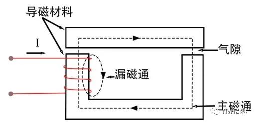
Figure 6.3 Magnetic circuit diagram
Typical magnetic circuit composition:
1. Magnetic source: energized coil or permanent magnet, which generates magnetic potential; magnetic potential is also called magnetomotive force, represented by F, which is the magnetic field stress of the magnetic circuit, similar to that in electricity The electromotive force or voltage, the unit is A*turn (ampere-turn).
2. High magnetic permeability iron core: the purpose is to concentrate the magnetic flux on the specified path and obtain a strong magnetic induction intensity, which is realized by using a soft magnetic material to make a core of a specified shape.
3. Air gap: There is an air gap between the stator and rotor of the motor, which is also a part of the magnetic circuit; some special magnetic circuits such as transformers may not have an air gap of.
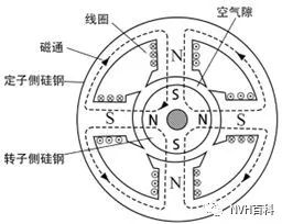
Figure 6.4 Motor magnetic circuit diagram
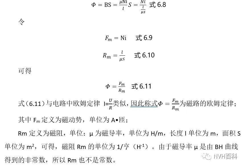
< p>6.2.2 Ohm's Law of Magnetic Circuit
Assume a uniform magnetic circuit: the cross-sectional area of the iron core is S, the circumference is l, the magnetic permeability is μ, and the Wind the energized coil with the number of turns N and the current i, and calculate its magnetic circuit characteristic quantity:
Figure 6.5 Uniform magnetic circuit
According to the Ampere loop theorem:

Assuming that there is no magnetic flux leakage in the magnetic circuit, the magnetic field all passes through the iron core, and the magnetic induction intensity B is equal to the cross-section of the iron core and is perpendicular to the cross-section S. The magnetic flux is defined as the product of the magnetic induction intensity B and the area S, referred to as the magnetic flux (Magnetic Flux), and the magnetic flux is a scalar, expressed by "Φ".
Magnetic flux Φ:

From the above magnetic circuit, you can draw its magnetic circuit diagram by referring to the circuit diagram:
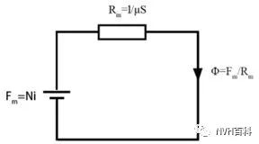
Figure 6.6 Magnetic circuit diagram
6.2.3 Kirchhoff's law of magnetic circuit
Kirchhoff's first law of magnetic circuit: Since the magnetic induction line is a closed curve, there is no head and no tail, Therefore, at any node in the magnetic circuit, the algebraic sum of the magnetic flux entering this place and the magnetic flux leaving this place should be zero, the expression is:
Kirchhoff's second law of magnetic circuit: from the law of full current, the magnetic pressure of each segment in any closed magnetic circuit The algebraic sum is equal to the algebraic sum of all magnetomotive forces around this loop, the expression is:

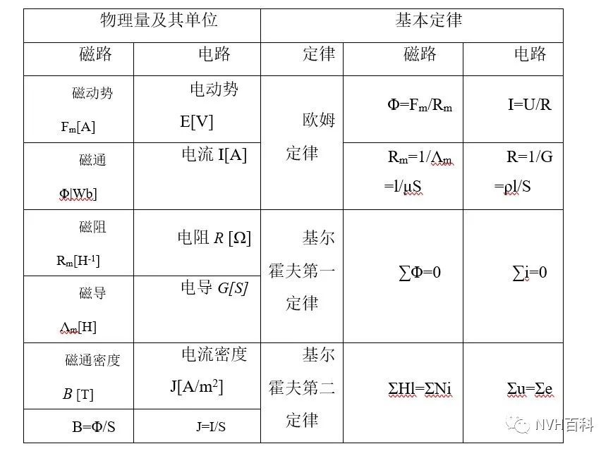
Because of the similarity between the magnetic circuit and the electric circuit, the analogy relationship between the basic parameters and laws of the two is shown in the following table:
Table 6.1 Analogy between the magnetic circuit and the electric circuit
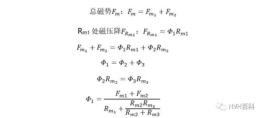
6.2.4 Series and parallel connection of magnetic circuits< /p>

There is a magnetic circuit as shown below
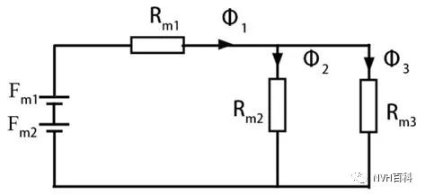
Figure 6.7 Series-parallel connection of magnetic circuit
Relationship between variables As follows:
6.3 air gap
6.3.1 Definition and characteristics of air gap
The electromagnet and the magnetic circuit structure of the motor contain air The air gap in the motor refers to the gap between the motor stator and the motor rotor.
The edge effect of the air gap and the flux leakage effect:
Since the reluctance of the air gap is several thousand times that of the iron core, the magnetic potential difference between a and b It is enough to cause the outward diffusion of the magnetic lines of force between the air gaps, resulting in the enlargement of the area that the magnetic lines of force pass through, that is, the edge effect of the air gap, and even a small amount of magnetic force lines do not pass through the air gap, directly from c to d, that is, magnetic flux leakage.
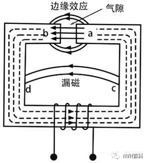
Figure 6.8 Edge effect of air gap and flux leakage< /p>
Due to the magnetic flux leakage effect of the air gap, the effective cross-sectional area of the air gap is not equal to the cross-sectional area of the iron core. In reality, if the length of the air gap does not exceed 15%-20% of the cross-sectional size of the iron core at the air gap And the iron core end faces on both sides of the air gap are parallel called short air gap, and its effective cross-sectional area can be calculated according to the empirical formula:
(1) The end faces on both sides of the air gap are coaxial, parallel, and have the same cross-sectional size, then the air gap The effective cross-section of the gap is the size. The length and width of the cross-section can be increased by an air gap length, and if it is circular, the diameter can be increased by an air gap length.

Figure 6.9 Equal-area air gap at both ends of the core
(2) If the two ends are coaxial, parallel, and cross-sectional If the difference is large, the effective section size of the air gap is to increase the side length of the small section by two air gap lengths, and if it is circular, increase the diameter of the small section by two air gap lengths; that is:

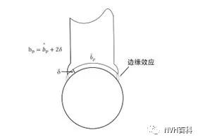
Figure 6.10 Air gaps with unequal areas at both ends of the core
6.3.2 Calculation of the magnetic circuit with air gap< /p>
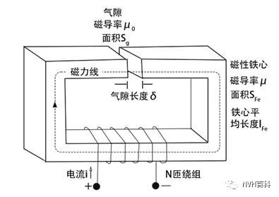
Figure 6.11 Magnetic circuit with air gap
Assuming that the air gap δ is small enough and there is no flux leakage in the magnetic circuit, calculate the magnetic potential, magnetic resistance, magnetic flux, and magnetic induction at the core and air gap:
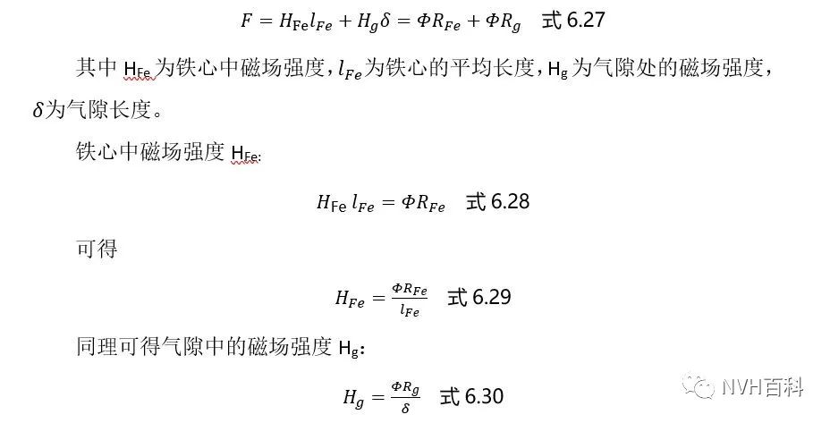
(1) Magnetomotive force : The magnetomotive force of the whole system is an N-turn winding passing through the current i, and the total magnetomotive force of the system is

(2) Reluctance and Permeance: Since the system is assumed to have no flux leakage, the magnetic field lines only pass through the core and the air gap, so the magnetic circuit can be simplified as the core and the air gap The magnetic circuit connected in series, the reluctance of the magnetic circuit is the sum of the core reluctance and the air gap reluctance;
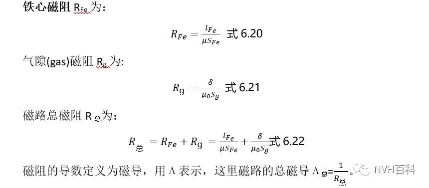
(3) Magnetic flux
The magnetic flux of the magnetic circuit is:
Magnetic flux is a continuous quantity, no matter in the air gap or in the iron core, the magnetic flux is equal.
(4) Magnetic potential drop and magnetic field strength
The product of the magnetic field strength of a certain section of the magnetic circuit and its path length is the magnetic potential drop of the magnetic circuit, which is numerically equal to the magnetic flux The sum of the product of magnetic resistance and the total magnetic potential drop connected in series on the magnetic circuit is the magnetomotive force.
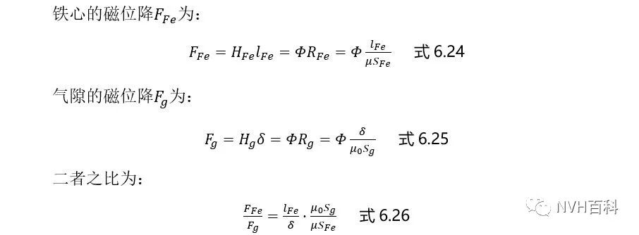
Because the magnetic permeability of the iron core is lower than that of the air Thousands of times (for example, silicon steel is about 8000 times that of air), it can be seen from formula 6.26 that although the air gap is short, the magnetic pressure drop of the air gap is generally much larger than that of the iron core.
(5) Magnetic flux density:
Assuming that the magnetic field lines are evenly distributed in the cross-section of the core and the air gap, define the magnetic flux density as the magnetic flux divided by the area of the magnetic circuit, and use B to express:
Combined with the introduction of the magnetic induction intensity above, the magnetic flux density and the magnetic induction intensity can be regarded as the same value, which is why the magnetic flux density Both the magnetic induction and the magnetic induction are represented by B.
According to formulas 6.33 and 6.34, it can be seen that the magnetic flux density at the core and the air gap is not equal.
According to the above calculations, several important quantities in the above magnetic circuit can be calculated using known quantities, including: current i, number of turns N, average length of iron core lFe, iron core Cross-sectional area SFe, core magnetic permeability μ, air gap length δ, air gap area Sg, vacuum magnetic permeability μ0 (here the air gap magnetic permeability is represented by vacuum magnetic permeability), as shown in Figure 6.11.
6.4 Equivalent of permanent magnet
6.4.1 Equivalent principle of permanent magnet in magnetic circuit
As a magnetic source, a permanent magnet is similar to a current, and will generate a corresponding magnetomotive force, but at the same time it is a part of the magnetic circuit, and because the permanent magnet has a demagnetization curve and a recovery curve, and the two curves of some permanent magnet materials are not the same Coincident, so the working state of the permanent magnet is very complicated. Here, it is assumed that the permanent magnet is a rare earth permanent magnet, and its demagnetization curve is close to a straight line, and the return line coincides with the demagnetization curve.
Assuming that the permanent magnet works in a constant magnetic field, it only needs to connect the permanent magnet in series or parallel to the magnetic circuit as a constant magnetic source, but when it works in an alternating magnetic field, such as The permanent magnet synchronous motor can be equivalent according to the method of equivalent magnetic flux or equivalent magnetic potential.
6.4.2 Equivalent magnetic flux
When the permanent magnet motor is running, the permanent magnet is equivalent to a constant magnetic flux source Φr and a constant The magnetic flux source connected in parallel with the flux permeance Λr: where Φr is the virtual intrinsic flux of the permanent magnet, which is a constant for a permanent magnet with a given performance and size:
Sm is the cross-sectional area of the magnetic flux provided by the permanent magnet for each pole; Br is the residual magnetic induction.
Λr is the internal permeability of the permanent magnet. For a permanent magnet with a given performance and size, it is also a constant:
hMp is the length (m) of the magnetization direction of the permanent magnet in each pair of pole magnetic circuits, μr is the relative recoil permeability, which is the inherent parameter, μ0 is the vacuum permeability.
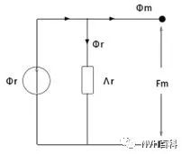
Figure 6.12 The permanent magnet is equivalent to a constant magnetic flux parallel connection Magnetic Permeance (Reluctance)
6.4.3 Equivalent Magnetic Potential
The above-mentioned magnetic flux source can also be equivalently transformed into a magnetomotive force source Fr and A magnetomotive force source connected in series with a constant internal permeability Λr:
For a permanent magnet of given performance and size, Fr is a constant:
Hc is the coercive force of the permanent magnet, hMp is the length of the magnetization direction of the permanent magnet in each pair of pole magnetic circuits, see the value of Λr superior.
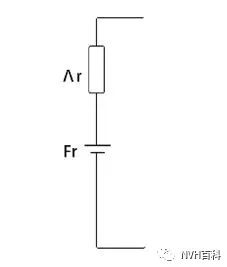
Figure 6.13 The permanent magnet is equivalent to a constant magnetic potential string Even permeance (reluctance)