-
Mail us
sale@tiger-transformer.com -
Phone us
(+86)15155183777 -


Mail us
sale@tiger-transformer.comPhone us
(+86)15155183777
As an uninterruptible power supply, UPS has been widely used in various industries such as chemical industry, transportation, railway, power plant, substation, metallurgy, nuclear power plant, mobile communication, control equipment and its emergency protection system. It is used for computer and computer network systems. Or electronic instrumentation equipment such as: various transmitters, solenoid valves, etc. to provide continuous, stable, uninterrupted power supply. The UPS power system is mainly composed of the following parts: the rectifier part for AC/DC conversion, the inverter part for DC/AC conversion, the inverter and bypass output switching circuit, and the energy storage battery part. As a special power electronic product, due to its unique circuit characteristics, in some abnormal power supply conditions, it will affect the front-stage power supply circuit and the rear-stage load. This paper analyzes a large-area failure phenomenon of a UPS post-stage instrument power board, finds out the cause, and reduces the loss caused by similar events to production.
Fault phenomenon
The raw material pretreatment device SIS, power station SIS and generator set CCS main rack and expansion rack among the instrument cabinets of a certain company, 6 pieces are powered by 1# UPS All the power supply cards of the instruments fail, the air switch corresponding to the power supply of the upper level trips, and the output of the DC power board disappears. After the accident, the inspection found that the varistor MOV1 of the 6 power supply cards inside the instrument had discharge traces.
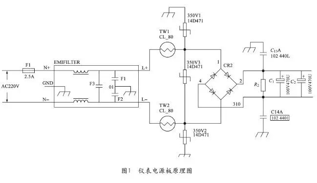
After on-site inspection, the UPS that supplies power to the instrumentation equipment is three-phase 380VAC input and 220VAC single-phase output. Its output 220VAC is not grounded. Under normal circumstances, the L and N of the UPS output are both 110VAC to the ground PE. Figure 1 is a schematic circuit diagram of the instrument system power card.
After the accident, contact the instrument supplier , The equipment manufacturer gives the following opinions:
The TN-S system is required for the AC220V power supply for instrumentation equipment. Since the output of the UPS is not grounded in the TN-S system, it is the cause of the burnout of the power board of the instrumentation equipment. When the voltage of the input terminal of the power supply fluctuates to the ground, the voltage of the N terminal and the L terminal will rise, causing the varistor to break down, causing a short-circuit current and causing the power circuit breaker to trip.
Is this conclusion accurate? Let's continue the analysis.
Several power supply modes of AC power supply AC220V
Several power supply forms of AC power supply AC220V are:
1**The wiring mode of the primary side is not considered, There are several wiring methods for single-phase AC220V**
In Figure 2, the voltage of L1 to ground is AC220V, and the voltage of N to ground is 0V. Meet the power supply requirements of single-phase AC220VTN-S system.
In Figure 3, the voltage to ground between L1 and L2 is 0, and the voltage between L1 and L2 is AC220V. Meet the IT system power supply requirements of single-phase AC220V.
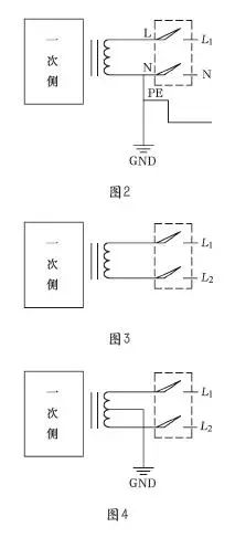
In Figure 4, the voltages of L1 and L2 to ground are It is 110AC, output 220VAC between L1-L2. Meet the power supply requirements of single-phase 220VACTT system.
In Figure 5, the ground voltage of L1 and L2 is 110AC, and the output between L1-L2 is 220VAC. Meet the power supply requirements of single-phase 220VACTN-S system.
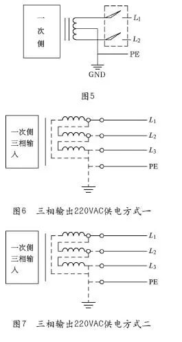
In Figure 6, the three-phase output 220VAC power supply mode is not considered for the wiring mode of the primary side. The output line voltage between a, b, and c is 220VAC, and the phase voltage cannot be output. Meet the three-phase or single-phase load 220VACIT power supply requirements.
In Figure 7, the three-phase output 220VAC power supply mode is not considered for the wiring mode of the primary side. The output line voltage between a, b, and c is 220VAC, and the phase voltage cannot be output. Meet the three-phase or single-phase load 220VACTN-S power supply requirements.
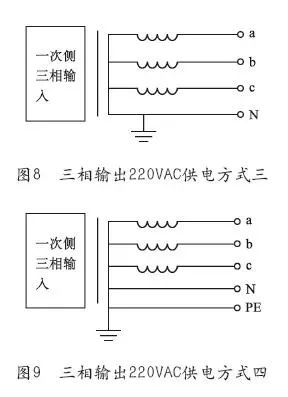
In Figure 8, the wiring method of the primary side is not considered , Three-phase output 220VAC power supply. The output line voltage between a, b, and c is 380VAC, and the output to the N line is 220VAC. Meet the 380/220VAC load TT power supply requirements.
In Figure 9, the three-phase output 220VAC power supply mode is not considered for the wiring mode of the primary side. The output line voltage between a, b, and c is 380VAC, and the output to the N line is 220VAC. Meet the 380/220VAC load TN-S load power supply requirements.
2TN-S Grounding System
2TN-S Grounding System
2TN-S Grounding System
strong>
The International Electrotechnical Commission (IEC) has made unified regulations on engineering power supply systems, which are collectively referred to as TT systems, TN systems, and IT systems. Among them, the TN system is divided into TN-C, TN-S, and TN-CS systems.
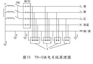
Among them, the TN-S power supply system is a power supply system that strictly separates the working zero line N from the dedicated protection line, called the TN-S power supply system, and its schematic diagram is shown in Figure 10. The characteristics of the TN-S power supply system are as follows:
1
When the system is running normally, there is no current on the dedicated protection line, but there is unbalanced current on the working zero line. The PE line has no voltage to the ground, so the zero protection of the metal casing of the electrical equipment is connected to the special protection line PE, which is safe and reliable;
2
The working zero line N is only used as Single-phase load circuit or three-phase unbalanced current flow;
3
The special protection line PE is not allowed to break, and it is not allowed to enter the leakage switch;
4
A leakage protector is used on the main line. The working zero line must not be repeatedly grounded, and the PE line is repeatedly grounded, but it does not pass through the leakage protector. Therefore, a leakage protector can also be installed on the TN-S system power supply main line ;
5
The TN-S power supply system is safe and reliable, and is suitable for low-voltage power supply systems such as industrial and civil buildings.
Fault Analysis
1Analysis of Filter Capacitor and Varistor Under Pressure
According to the schematic diagram of the power board in Figure 1:< /p>
1
When the UPS output is not grounded, that is, when the power supply mode shown in Figure 3, Figure 6, and Figure 7 is used.
The O1 point in Figure 1 is grounded, which is zero potential. Capacitors F1 and F2 need to bear 110V voltage, F3 bears 220V voltage, varistor MOV1 and MOV2 each bear 110V voltage, and varistor MOV3 bears 220V voltage. This also explains why there are 110V voltages between L-PE and N-PE when the field system is normal.
2
When the UPS output is grounded, use the two grounding power supply methods shown in Figure 4, Figure 5, and Figure 9 (according to TN-S). Same as 4.1, capacitors F1 and F2 need to bear 110V voltage, F3 bears 220V voltage, varistor MOV1 and MOV2 each bear 110V voltage, and varistor MOV3 bears 220V voltage.
3
When the UPS output is grounded, that is, when the power supply mode shown in Figure 2 and Figure 8 (conforming to TN-S) is adopted.
The O1 point in Figure 1 is grounded, which is zero potential. Capacitor F1 will withstand 220V voltage, F2 will withstand 0V voltage, F3 will still withstand 220V voltage, MOV1 will withstand 220V voltage, MOV2 will not withstand voltage, and MOV3 will still withstand 220V voltage. Capacitors F1 and MOV1 are prone to overload and burn out.
The above analysis shows that if the power supply form shown in Figure 2 and Figure 8 (according to TN-S) is adopted, the capacitor F1 and the varistor MOV1 will be easily burned. If the power supply forms shown in Figure 3, Figure 4, Figure 5, Figure 6, Figure 7, and Figure 9 (according to TN-S) are used, the failure phenomenon of the power board in this paper is not easy to occur. Therefore, whether the power supply form adopts the TN-S system is not the key cause of the failure. However, through analysis, it can be preliminarily determined that the grounding conditions of the UPS have changed during operation, causing the power board components of the subsequent stage to burn out.
2The instantaneous power failure phenomenon recorded by 2#UPS
After further extraction of the original record, we found a phenomenon that is related to 1#UPS The SIS internal power supply cards powered by 2# UPS working at the same time recorded the instantaneous power loss phenomenon. Both UPS1 and UPS2 automatically switched to bypass power supply at that time. The post-stage instrument power supply of UPS1 is burnt out, and the post-stage instrument power supply of UPS2 is normal. The outputs of UPS1 and UPS2 are not grounded, which meets the requirements of Figure 1. MOV1 and MOV2 each bear a voltage of 110V, and MOV3 bears a voltage of 220V. When UPS1 is bypassed, the N line of the bypass power supply is grounded, so the power supply mode may change from the original figure 3, 4, 5 to the power supply form in figure 2 (three-phase input and single-phase output UPS used on site), so F1 bears 220V voltage, F2 bears 0V voltage, F3 still bears 220V voltage, MOV1 bears 220V voltage, MOV2 does not bear voltage, MOV3 still bears 220V voltage, and MOV1 burns out. After 2#UPS switching, the circuit works normally.
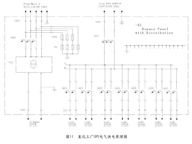
Therefore, it is the key to this failure to carefully review and check the wiring of the bypass system of UPS1, especially the neutral wire and ground wire. According to this idea, we found that the output N line of the bypass transformer of UPS1 is indeed grounded, as shown in Figure 11, which confirmed our analysis results.
3What needs attention in UPS applications Question
The output voltage of the UPS is AC220V, 0V; or AC110, AC110V. This value is the effective value of the voltage in the physical quantity, and the maximum peak-to-peak voltage may reach 1000V or more. This is because there are high-power transistors such as GTR or insulated gate bipolar transistor IGBT inside the UPS, the output of which is mostly a SPWM voltage waveform, chopping will generate a peak voltage (L×di/dt), and its peak-to-peak voltage value will reach 1000V or above. After the UPS jumps to bypass operation, the grounding condition changes suddenly, and the maximum voltage value added to the varistor and filter capacitor will increase several times, so it is not surprising that they burn out. Therefore, it is recommended to add an output isolation transformer to the rear end of the UPS output to reduce the impact of voltage peak-to-peak glitches on the rear-stage load.
Conclusion
Although UPS uninterruptible power supply has been widely used as a special power electronic power supply equipment, for the front and back stage electrical equipment, power load, System grounding and other comprehensive application issues, various industries put forward some technical conditions and operating specifications and standards according to their own characteristics and requirements, but these technical conditions, specifications and standards are not completely unified, and sometimes even completely contradictory, which requires our electrical workers , can comprehensively and deeply understand the characteristics of the electrical, UPS, post-stage instrumentation equipment, and grounding power supply system in practical applications, conduct specific analysis of specific problems, and propose operation and wiring methods that meet actual needs, so as to ensure the safety and reliability of power supply system operation .
Attach the requirements of UPS grounding methods in some countries or industry standards:
1**About whether the output of the secondary side of the UPS can be grounded* *
Refer to Article 10.2.15 of DL/T5136-2012 "Technical Regulations for Secondary Design of Substations in Thermal Power Plants": the power distribution system can be ungrounded or grounded. The power requirements of the thermal system are determined. The article is explained as follows: "The use of an ungrounded system can improve the reliability of power supply for important electrical equipment, and the use of a grounding system can meet the grounding requirements of some DCS manufacturers for AC power and reduce the neutral-ground voltage."
< p> "UPS main circuit has various connection methods. When the UPS is grounded: when the bypass is isolated, the incoming N wire is electrically isolated from the UPS output N wire, so the output N wire is connected to the PE wire and to the common ground. When the bypass is not isolated, the N wire of the incoming line is directly connected to the N wire of the UPS output, so the N wire of the UPS output should not be grounded again, and it is still the ground system after the UPS.”
"Whether the UPS output N line needs to be grounded should be determined according to the UPS wiring form, reliability, etc., and comprehensively consider the requirements of the thermal system for power supply. The current national standard GB50174-2008 "Electronic Information System Computer Room Article 8.1.10 of the Design Specification states that “when the neutral-ground voltage does not meet the requirements of the load (generally the neutral-ground voltage should be less than 2V), measures should be taken to reduce the neutral-ground voltage.” After investigation, some DCS factories The AC 220V power supply has grounding requirements, such as ABB and FOXBORO; some DCS factories have no requirements for this. When the DCS power supply needs the neutral line to be grounded, the neutral line of the UPS power distribution system can be grounded or an isolation transformer can be added to the DCS. Realization of secondary side grounding. Adopting an ungrounded system can reduce the number of power outages and improve the reliability of power supply. The system can reduce the zero-ground voltage to meet the power requirements of some equipment. In addition, when the thermal power supply is ungrounded and the security power supply is grounded, some fast power switching circuits cannot correctly monitor the voltage on both sides and cause switching failure. In this case, the grounding method may also be considered.”
According to the above explanation, the “Sinopec Production Equipment Process Control Instrument Power Supply System Technical Management Regulations” stipulates that “the neutral point of UPS output Specifications for Design of Instrument Grounding (SH-T3081-2003) stipulates that "the power supply in the control room shall adopt the TN-S system", and the requirements for the grounding method of UPS are all one-sided.
When the UPS load is a single-phase load, the UPS with a three-phase output of 380/220V cannot use the neutral point ungrounded method. When the 380V/220V three-phase output UPS adopts the neutral point ungrounded mode, under normal circumstances, as long as the potential of the neutral point, that is, the N line, does not exceed the standard, the 220V load of the UPS can operate normally. When a phase such as A phase ground fault occurs, the non-faulted B and C phase N line voltage increases from 220V to line voltage 380V, and at this time the 220V connected between BN and CN The load is all burned.
Therefore, the ungrounded neutral point of UPS output is only suitable for single-phase output UPS or only 380V load.
2Whether an isolation transformer is installed on both sides of the UPS AC input and output
DL/T5136-2012 "Secondary Design of Thermal Power Plant Substation Article 10.2.15 of the Technical Regulations stipulates: UPS AC input and output sides should be installed with isolation transformers. The article is explained as follows:
1
Because the secondary winding of the isolation transformer adopts the Y-type connection method, a new neutral line is generated after the neutral point is grounded, thereby reducing the zero-ground voltage.
2
The output isolation transformer can filter out a large number of low-order harmonics at the load end, reduce high-frequency interference, and greatly attenuate high-order harmonics.
3
Enhance the overload and short circuit protection capability and isolate the safe load. During normal operation of the UPS, if a large short-circuit current is encountered, the transformer will generate a reverse electromotive force, which delays the impact of the short-circuit current on the load and the inverter and protects the load and the UPS host.
4
The output isolation transformer has the ability of "passing AC and resisting DC", such as no output isolation transformer, once the insulated gate bipolar transistor (IGBT) of the inverter bridge arm If it is broken down and short-circuited, the high DC voltage of the bus will be added to the load, which will endanger the safety of the load.
Article 8.1.10 of GB50174-2008 "Code for Design of Electronic Information System Computer Room" stipulates that when the potential difference between the neutral line and the PE line at the output end cannot meet the requirements for the use of electronic information equipment, an isolation transformer.
The potential difference between the neutral line and the PE line is called "zero-ground voltage". When the "zero-ground voltage" is higher than the allowable value of electronic information equipment, it will cause electrical hardware failure and burn the equipment ; cause malfunction of control signal; affect communication quality... Therefore, when the "zero-ground voltage" does not meet the requirements of the load (generally "zero-ground voltage" should be less than 2V), measures should be taken to reduce the "zero-ground voltage" ". For TN systems, it is an effective way to reduce the "zero-ground voltage" by installing an isolation transformer at the output of the UPS. When selecting the protection switch of the isolation transformer, the excitation inrush current when the isolation transformer is switched on should be considered.