-
Mail us
sale@tiger-transformer.com -
Phone us
(+86)15155183777 -


Mail us
sale@tiger-transformer.comPhone us
(+86)15155183777
A transformer (transformer) is a device that converts electrical energy into magnetic energy, and then converts magnetic energy into electrical energy.
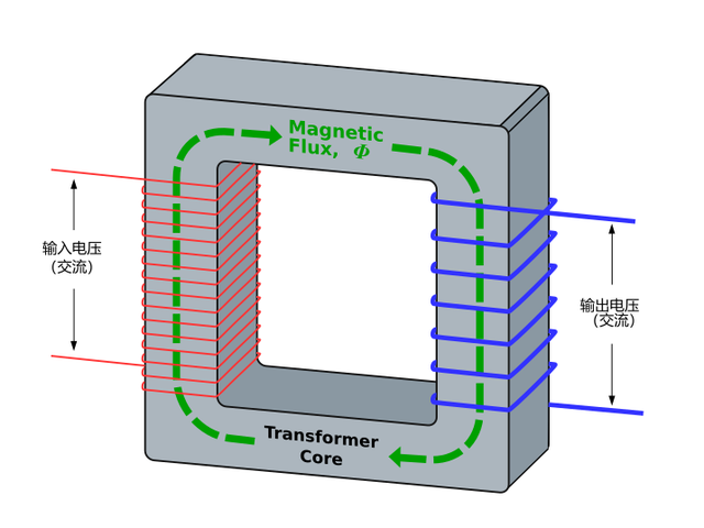
Transformer diagram
The transformer can be upgraded Voltage, step-down, can also keep the voltage constant, play the role of isolation.
That is to say, a transformer can get another voltage from one voltage.
Basically, a transformer has a bunch of wires wound around an iron or ferrite core.
Transformers only work on alternating current (boosting, stepping down, equal voltage isolation), and do not work on direct current.
Generally, transformers on the market have two output specifications, single output and dual output.
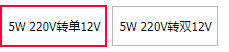
Two output specifications
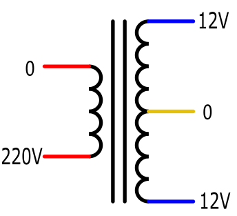
As above As shown in the figure, 220 V to 12 V is 220 V to 12 V. Its input and output are two wires, which is easier to understand. What is more puzzling is the dual output. For example, the above 220 V to dual 12 V means to output two 12 V, a total of three output lines, there is a common line called the center tap, as shown in the above figure The yellow line is the center tap line. The two 12 V can be synthesized into a 24 V voltage, which will be discussed later.
The "5VA" marked on the transformer is an important parameter of the transformer, indicating the power of the transformer. In most cases, especially for small power transformers, VA can be understood as the unit of success rate: watts, That is, 1VA means 1 watt. 5VA means the power of the transformer is 5 watts.
The structure diagram of the transformer with dual 12-volt output is as follows:
 < /p>
< /p>
Structure Diagram of Dual Output Transformer
If you want to use 12V ground output, connect the ground wire to the yellow wire, and use any blue wire to get 12V output. But this connection only uses half of the rated power of the transformer.
If you want to use 24V output, connect the ground wire to any blue wire, the output is 24V, and ignore the yellow tap in the middle.
Because the transformer secondary coil is isolated from the primary coil, an oscilloscope can be used to measure the output of the secondary coil. Note: Do not connect the ground clip of the oscilloscope to the terminal of the primary coil, otherwise the oscilloscope may be burned.
From the waveform measurement results, it can be seen that the root mean square (RMS) voltage and the peak-to-peak (Peak to Peak) voltage are different. The 24 volt output voltage we actually measured was 26.4 volts. The rms voltage of 26.4 volts tells us how much voltage you can put out to the load. The peak-to-peak voltage of 71.5 volts tells us the maximum voltage our downstream circuit components need to be able to handle. For this purpose, we need capacitors with a minimum voltage rating (withstand voltage) of 100 volts to handle a peak-to-peak press of 71.5 volts.
Next, we use an oscilloscope to measure the waveform of the 12-volt dual output
You can see that the polarity of the two waveforms is just opposite. They have a peak-to-peak voltage of 35.3 volts, about half of the previous 71.5 volts peak-to-peak.
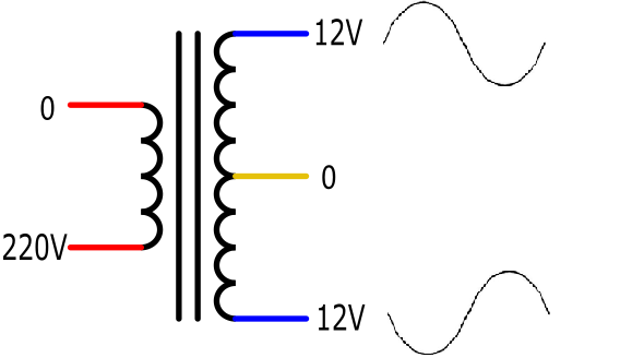
Double output waveform diagram
Therefore , using a transformer with a center tap allows you to get a negative voltage as well as a positive voltage. This is useful when designing dual-rail power supplies with positive and negative voltage outputs.
Using the above dual 12 volt output, plus two capacitors and two diodes, a simple positive and negative 18 volt dual-rail DC power supply is born.
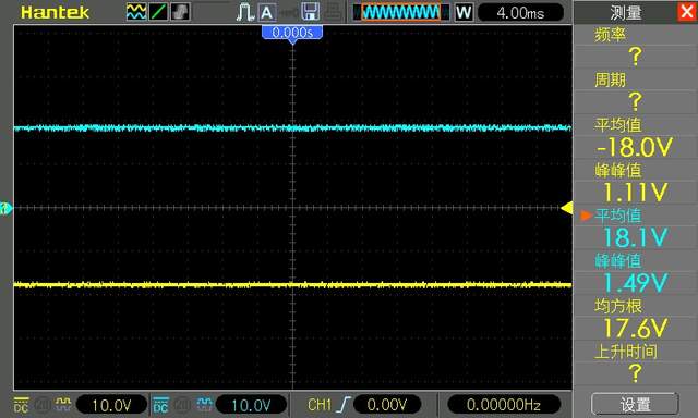
Double-rail power waveform