-
Mail us
sale@tiger-transformer.com -
Phone us
(+86)15155183777 -


Mail us
sale@tiger-transformer.comPhone us
(+86)15155183777
1. Circuit Overview
Joule Thief can drain the energy of a battery, even an old battery that is usually so-called "used up". It can also continue to exert "residual heat". Therefore, it is metaphorically compared to a thief of "joules" of electrical energy.
The magic is: an old AA battery, after being "used up", still has a voltage of about 1V, while LEDs require a driving voltage of 2~3V, and the Joule thief can boost the voltage. Let the old battery continue to power the LED!
2. Principle Analysis
The Joule Thief is essentially a (self) oscillation circuit, which converts the low voltage of the battery into higher voltages. High voltage pulses with very high frequency (several KHz). The pulse lights up the LED, and the "afterglow effect" in the eyes makes people feel that the LED continues to light up.
In 2002, Clive Mitchell presented an oscillation boost circuit constructed from modern electronic components, which included a transformer, a transistor, a resistor, an LED and a battery, and combined this The circuit is officially named "Joule Thief":
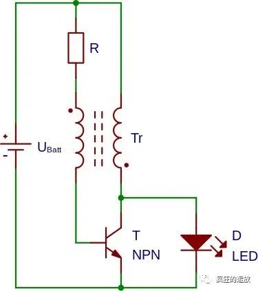
Picture 2-Joule Thief Circuit Diagram
Among them, the battery is AA battery (AA battery) 1.5 V, the resistor value is1 kΩ, the transistor can be 2N3904, BC547B, 2N2222 and other conventional models, and the LED driver The voltage is 2.33.2V or even higher.
If you look at the voltage waveform on the LED, you will see pulses. The voltage is clamped to the LED driving voltage, with a duty cycle of about 30% and a frequency of about 40KHz:
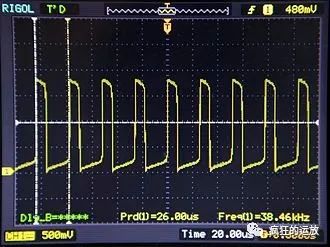
Figure 3-Joule Thief Oscillation Pulse
Although the circuit looks Simple, but its working process is not simple, and it is not easy to explain. But it remains true to its roots, and the most critical component is the "inductor" on the transformer.
Here, I will first give a circuit that purely relies on "inductance" to boost the lighting (flash). I believe it is easy for everyone to understand:
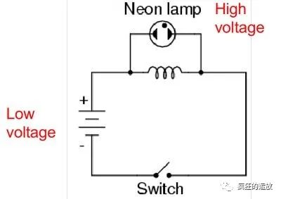
Figure 4-Inductor Boost Lighting
Among them:
The switch is closed, the inductor stores energy, and the light does not light up;
The switch is opened, the inductor releases energy, and the light flashes; (The complete process is described as: the circuit current is interrupted, and the current on the inductor cannot change suddenly. In order to maintain the current, it rises The high voltage opens the circuit of the lamp, but because the energy is very small, it is only lit for a moment)
We can do an experiment as follows:

Figure 5-Inductor Boost Lighting Experiment
In the picture, the left side is homemade Inductor, the switch you keep pressing in the lower right corner is. Try to imagine that if a person can press the switch desperately at a very high speed, then the LED will be always bright in human eyes. Please remember this core idea when understanding the following Joule Thief working process.
3. Working process
A. Component connection diagram
For the sake of intuition, the diagram The schematic diagram in 2 is changed to a component connection diagram:
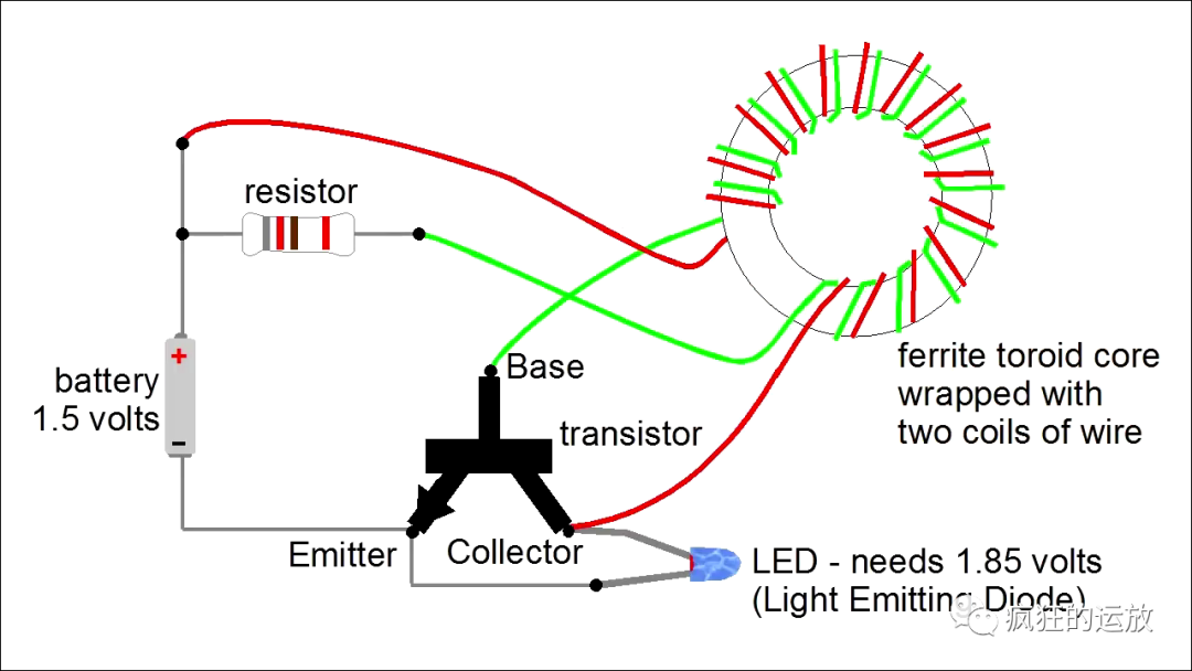
Figure 6 - Joule Thief’s electronic component connection diagram
Among them:
The battery can be an ordinary AA battery;
Resistor It is a 1KΩ current limiting resistor that provides current on the BE path of the transistor;
The transformer is wound with two wires on the magnetic ring core. Note that the upper end of the red wire is connected to the positive pole of the power supply, and the lower end of the green wire is connected The positive terminal of the power supply (ignoring the resistance), this is consistent with the drawing of the same terminal of the transformer in Figure 2;
The LED is connected in parallel on the triode CE path;
B. Knowledge points about triodes
If you are not familiar with triodes, you can understand it as a smaller current on the BE path and a larger current on the CE path.
In the cut-off state, there is no current or a very small current passing through the BE path, and there is no current passing through the CE path.
Under normal conditions, the triode has the ability to amplify current, and the amplification factor is β. That is, the CE path current has a beta multiple relationship with the BE path current. It can be said that the BE path current controls the CE path current. When the BE path current is small, the CE path current is also small; when the BE path current is large, the CE path current is also large; and there is a multiple relationship between the two.
In the saturated state, the multiple relationship between the currents on the BE path and the CE path no longer holds. At this time, no matter how large the BE path current is, the CE path current cannot reach β times, but can only be maintained at a constant value. This constant value is determined by the power supply output capability or the resistance on the CE path. This means that the CE path current has a limit and will not increase infinitely. Of course, the BE path also has limits. There is a 1KΩ current-limiting resistor on its path.
C. Working process
When initially powered on, the transistor is in a cut-off state.
A small part of the current passes through the resistor and green coil and enters the triode BE path. This causes the triode CE path to open slightly, so some current flows through the red coil and then into the triode CE path.
At this time, the transistor is in an amplified state, and the current flowing through the CE path and the red coil is greater than the current flowing through the BE path and the green coil coil current. The greater the current, the greater the magnetic flux generated in the coil. Therefore, on the magnetic ring core of the transformer, the magnetic flux generated by the red coil current is dominant.
Since the red coil and the green coil share the magnetic flux, the red coil current has been getting larger, and the magnetic flux has also been getting larger. For The change in magnetic flux, the green coil will generate an induced electromotive force. The direction of this induced electromotive force is opposite to the voltage of the red coil as the load (can be analyzed from Lenz's law, the same terminal of the transformer, etc.), so the induced electromotive force superimposes the power supply voltage itself, making the voltage drop of the triode BE path larger (see the figure below). The BE path current also becomes larger, which causes the triode CE path current to further increase.
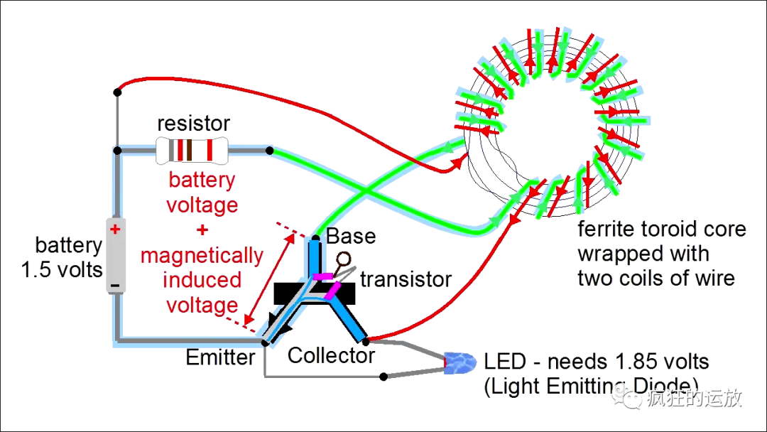
Figure 7 - Positive feedback quickly saturates the transistor
The above 3 and 4 are positive feedback, but the CE path current will not increase without limit , eventually the transistor enters a saturated state, and the current on the CE path no longer changes.
The current on the CE path does not change, the magnetic flux does not change, so the induced electromotive force of the green coil disappears, and the pressure on the BE path The drop becomes smaller, and the BE path current also becomes smaller accordingly.
The current on the BE path of the triode becomes smaller, which means that the current on the CE path will also become smaller.
The CE path current of the transistor becomes smaller, and the magnetic flux of the red coil also becomes smaller. The induced electromotive force generated by the green coil hinders its change. This time the induced electromotive force is in the opposite direction to the power supply voltage, which reduces the voltage drop on the BE path of the transistor, thereby reducing the current on the BE path (see the figure below).
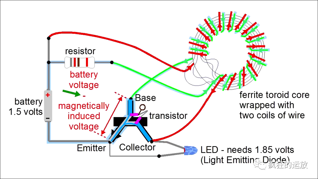
Figure 8 - Positive feedback makes the transistor cut off quickly
The above 7 and 8 are also positive feedback, which makes the transistor enter the cut-off state.
The transistor is cut off, the red coil acts as an inductor, its current path is interrupted, the current has nowhere to release, and it rises High voltage at both ends opens the LED path and lights up the LED (the principle is similar to Figure 4).
After the energy is released, the induced electromotive force of the green coil disappears, and the BE path can be positively biased by the power supply. A new round of process begins over and over again.
So the LED can be illuminated periodically due to positive feedback. The transistor is constantly being turned on (saturated) and cut off quickly. At this high level, Under the oscillation of frequency, the LED appears to be always bright to the naked eye.
4. Experimental results
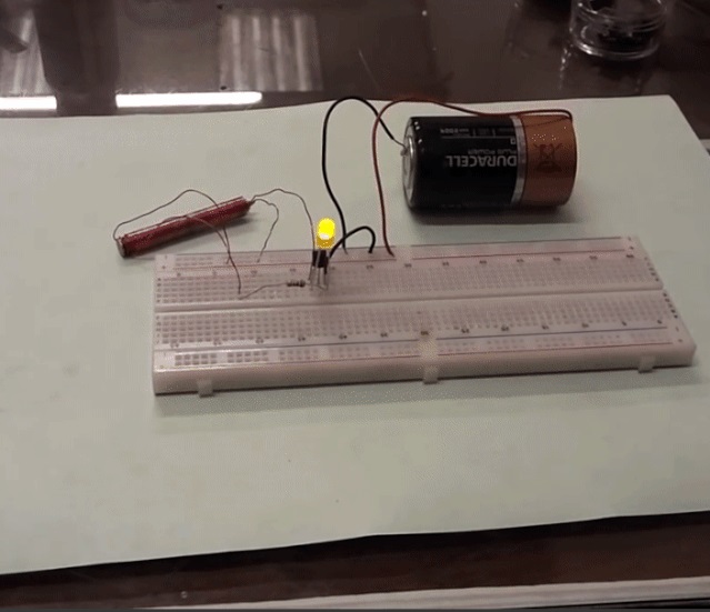
Figure 9 - Joule Thief Experiment Effect
Summary:
This circuit uses a combination of a transformer and a transistor so that the transistor is always cut off - It oscillates continuously between saturation states, and positive feedback intervenes in each oscillation, so the oscillation frequency is very high. High-frequency current changes trigger high-frequency magnetic field changes, which in turn can induce a voltage higher than the power supply to light up the LED.