-
Mail us
sale@tiger-transformer.com -
Phone us
(+86)15155183777 -


Mail us
sale@tiger-transformer.comPhone us
(+86)15155183777
Three-phase transformer is a common power conversion device and is widely used in power systems. It can convert electrical energy between high and low voltages, while also providing functions such as phase shifting and voltage regulation.
Three-phase transformers have the advantages of simple structure and reliable operation, and play an important role in power transmission and distribution. In this article, we will introduce the working principle of three-phase transformers and the differences in wiring configuration and application. We hope it will be useful to you.
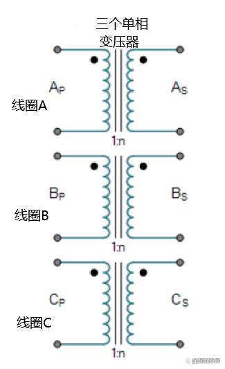
If we take three single-phase transformers and connect their primary windings to each other and their secondary windings to each other in a fixed configuration, we can use these transformers on a three-phase supply.
Three-phase power is used for power generation, transmission and distribution and for all industrial purposes. Three-phase power has many electrical advantages over single-phase power. When considering a three-phase transformer, we have to deal with three AC voltages and currents that are 120 degrees apart in phase time.
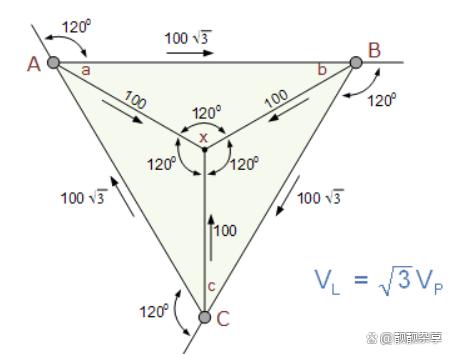
Where: Vl is the line voltage, Vp is the phase voltage.
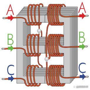
Three-phase transformers can be constructed by connecting three single-phase transformers together to form a so-called three-phase transformer bank, or by using a pre-assembled and balanced three-phase transformer consisting of three pairs of single-phase transformers. transformer to construct. Phase windings mounted on a single laminated core.
The advantage of building a single three-phase transformer is that, for the same kVA rating, it is smaller, cheaper and lighter than three separate single-phase transformers connected together because of the copper core and iron The core is used more efficiently. The method of connecting the primary and secondary windings is the same whether using only one three-phase transformer or three separate single-phase transformers.
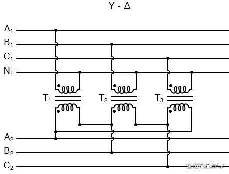
The primary and secondary windings of the transformer can be as shown Connected in different configurations to meet almost any requirement. For three-phase transformer windings, three connection types are possible: "star" (star), "delta" (mesh) and "interconnected star" (zig-tooth).
The combination of the three windings can be primary delta connection and secondary star connection, or star-delta, star-star or delta-delta, depending on the purpose of the transformer. When transformers are used to provide three or more phases, they are often called polyphase transformers.
Three-phase transformer star and delta configuration
What do "star" and "delta" mean when dealing with three-phase transformer connections? A three-phase transformer has three sets of primary and secondary windings. Depending on how these winding sets are interconnected determines whether the connection is a star or delta configuration.
The three available voltages are themselves 120 electrical degrees apart from each other and determine not only the type of electrical connections used on the primary and secondary sides, but also the flow of current in the transformer.
Connect three single-phase transformers together, three The magnetic flux in the transformer is out of phase by 120 degrees of time. For a single three-phase transformer, there are three magnetic fluxes in the core, with a time phase difference of 120 degrees.
The standard method of marking three-phase transformer windings is to mark the three primary windings with the capital letters A, B, and C to represent the three individual phases: yellow, green, and red. The secondary windings are marked with lowercase letters a, b and c. The ends of each winding are usually labeled 1 and 2, so for example, the ends of the second winding of the primary would be labeled B1 and B2, while the third winding of the secondary would be labeled c1 and c2.
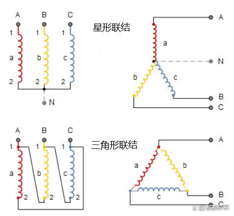
Usually used on three-phase transformers to use symbols to indicate the The type of connection, uppercase Y indicates star connection, D indicates delta connection, Z indicates interconnected star primary winding, and lowercase y, d and z indicate the respective secondary windings.
Advantages and Disadvantages of Delta and Star Transformers
High voltage transformers with star connection have the advantages of lowering the voltage on a single transformer, reducing the number of turns required and The advantage of increasing conductor size makes coil windings easier to insulate and cheaper than delta transformers.
Nonetheless, the delta-delta connection has a big advantage over the star-delta configuration, namely that if one of the three transformers in a set of three transformers fails or is disabled, the remaining two will continue to provide a capacity equal to Approximately two-thirds of the original output of the transformer unit.
One disadvantage of delta-connected three-phase transformers is that each transformer must be wound around the full line voltage and 57.7% of the line current. The higher number of turns in the winding, combined with the insulation between the turns, requires a larger and more expensive coil than a star connection. Another disadvantage of a delta-connected three-phase transformer is that there is no "neutral" or common connection.
A star connection requires the use of three transformers, and if any one transformer fails or fails, the entire group may fail. However, star-connected three-phase transformers are particularly convenient and economical in distribution systems because the fourth conductor can connect the neutral point (n) which is the secondary of the three star connections.
Transformer is one of the indispensable components in the power system, which plays an important role in power transmission and distribution. Through reasonable wiring methods and correct operating status selection, we can effectively utilize the function of the transformer to provide stable and efficient power supply.