-
Mail us
sale@tiger-transformer.com -
Phone us
(+86)15155183777 -


Mail us
sale@tiger-transformer.comPhone us
(+86)15155183777
Resonant transformers can effectively suppress high-frequency harmonics in the power system, thereby reducing electromagnetic interference in the power system and improving the stability and reliability of the power system. In addition, the resonant transformer can also effectively suppress low-frequency harmonics in the power system, thereby improving the efficiency of the power system.
The principle of the resonant transformer is to use the characteristics of the transformer's magnetic core and coil to generate an oscillating current at both ends of the transformer, thereby suppressing harmonics in the power system. The characteristics of the magnetic core and coil of the resonant transformer enable it to effectively suppress high-frequency harmonics in the power system, thereby improving the stability and reliability of the power system.
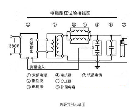
When the loop frequency f=1/2π√LC, the loop resonates. At this time, the voltage on the test sample is Q times the output voltage of the high-voltage end of the excitation transformer. Q is the system quality factor, that is, the voltage resonance multiple, which is generally from tens to more than a hundred. First, adjust the output frequency of the variable frequency power supply to cause series resonance in the loop, and then adjust the output voltage of the variable frequency power supply under the condition of loop resonance to make the voltage on the test sample reach the test value. Due to the resonance of the circuit, the smaller output voltage of the variable frequency power supply produces a higher test voltage on the test sample CX.
The frequency conversion resonance test device is mainly used in the following aspects:
1. AC withstand voltage test of 6kV-500kV high-voltage cross-linked cables
2. 6kV-500kV Power frequency withstand voltage test of transformer
3. AC withstand voltage test of GIS and SF6 switch
4. AC withstand voltage test of generator
5. AC withstand voltage test of other high-voltage power equipment such as busbars, bushings, and transformers.
Working principle of resonant transformer. I am currently experimenting with the resonant transformer pictured below.
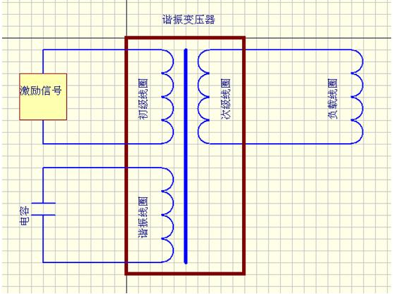
The excitation signal is a sine wave from a typical H-bridge drive circuit and is input into the primary coil.
A load coil is connected to the outside of the secondary coil for transmitting signals.
An adjustable capacitor is connected to the outside of the resonant coil. During the experiment, the size of the capacitor must be adjusted to maximize the peak-to-peak voltage on the load coil.
The primary, secondary and resonant coils are wound together in a magnetic pot.
That's basically the case. Although my goal is very simple, which is to adjust the turns ratio and capacitance value of each coil to maximize the voltage on the load coil, but due to the large number of variables involved, my theoretical analysis of the resonant transformer is not deep, so There has never been a clear direction.