-
Mail us
sale@tiger-transformer.com -
Phone us
(+86)15155183777 -


Mail us
sale@tiger-transformer.comPhone us
(+86)15155183777
1. EMI regulations and test specifications
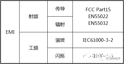
Full electromagnetic compatibility means that the equipment or system meets the requirements in its electromagnetic environment and does not cause any equipment in its environment Capability of intolerable electromagnetic interference. Table 1 applies to the external interference (EMI) of the power supply.
Table 1 EMI Standard
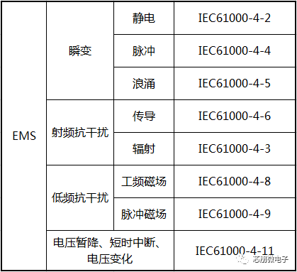
The immunity (EMS) of the power supply to external disturbances applies to the standards in Table 2.
Table 2 EMS Standard
There is a close relationship between EMI and EMS. This article mainly discusses the conduction and radiation of radio frequency. The frequency test range is 150k-1GHz. The latest standard EN55032 clearly stipulates two test voltages of 110Vac and 230Vac. The EMI test methods and limits are shown in the figure below .
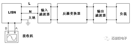
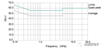
Figure 1 Conduction Test Method and Limits
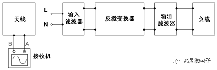
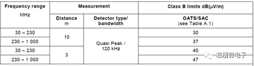
Figure 2 Radiation test methods and limits
It can be seen that conduction test has a path, and interference is transmitted to LISN through conduction current or displacement current; while radiation test has no path, and interference is transmitted through space alternating electromagnetic field spread.
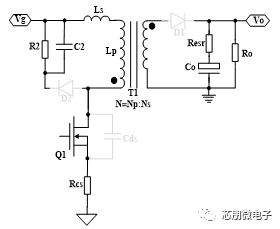
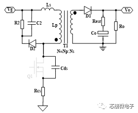
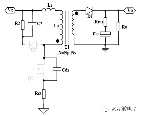
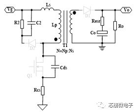
2. Time-frequency domain analysis method of flyback converter
Piecewise linearization into time domain analysis method of switching converter, as shown in Figure 3 It shows that the flyback converter can be divided into four sections for analysis.
T1 magnetization mode
Tr transmission mode
T2 degaussing mode
T3 Oscillation Mode
Figure 3 Flyback Converter Four-stage Working Mode
In a switch At the end of the cycle, the energy stored in the transformer has not been released, and there is no T3 oscillation mode, which is defined as continuous conduction mode (CCM), otherwise it is called discontinuous conduction mode (DCM).
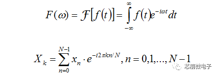
Fourier transform is a frequency domain analysis method for switching converters. It is divided into continuous Fourier transform and discrete Fourier transform, which are defined as follows:
The time-frequency domain simulation waveform of the main switching tube of the flyback converter is shown in Figure 4.
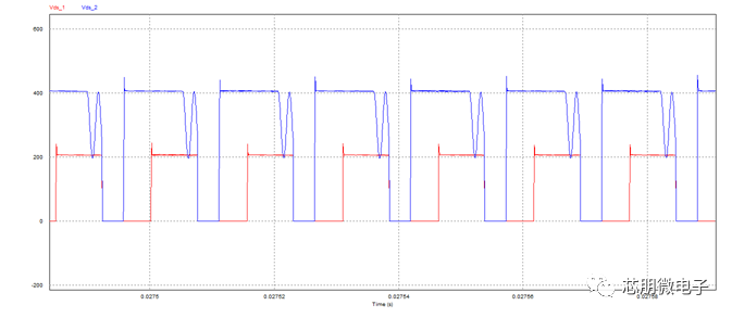
(a) Vds time domain waveform
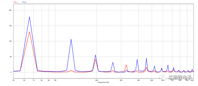
(b) Vds spectrum distribution
Figure 4 Flyback converter CCM and DCM time-frequency domain waveform
It can be seen that the spectral components of the switching waveform are centered on integer multiples of the switching frequency and the amplitude changes significantly with the working mode; the working mode is to cause 110Vac and The main reason for the difference in the EMI test results of 230Vac.
3. EMI theoretical basis and rectification measures
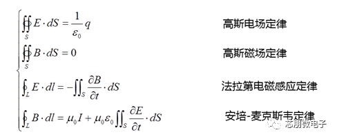
Maxwell's equations are the theoretical basis for analyzing EMI, Gaussian electric field and magnetic field laws describe the electric field and magnetic field Properties: Electromagnetism is not completely symmetrical, there is no magnetic monopole but a single charge, where there is N, there is S, and the magnetic field lines are closed. Faraday's law of electromagnetic induction states that a changing magnetic field produces an electric field. Ampere-Maxwell's law points out the existence of conduction current and displacement current, where displacement current is the current generated by the change of electric field with time, which is the basis of quantitative analysis of conduction.
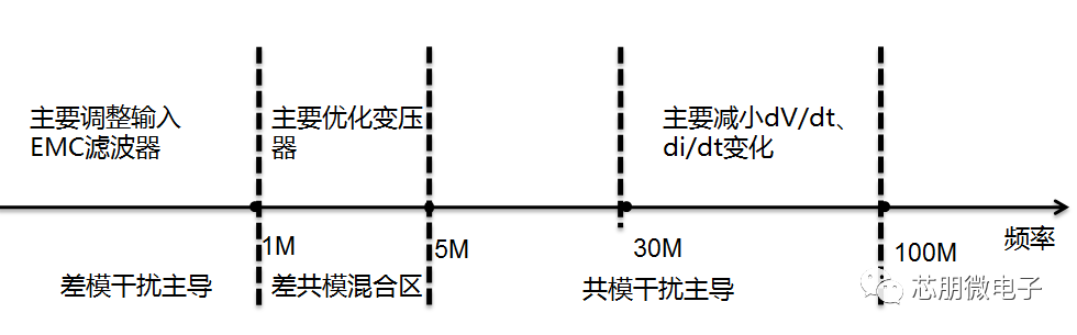
According to the propagation path of the interference signal in the switching power supply It is divided into differential mode interference and common mode interference: differential mode interference refers to the interference between L line and N line, and common mode interference refers to the interference between L line or N line and PE.
The EMI rectification measures of the flyback switching power supply are summarized as follows.