-
Mail us
sale@tiger-transformer.com -
Phone us
(+86)15155183777 -


Mail us
sale@tiger-transformer.comPhone us
(+86)15155183777
About the topic of the motor position sensor, the following two questions are often asked, and I will sort them out here:
What is "hardware decoding"?
What is "software decoding"?
The resolver position sensor has 6 lead connectors, which are: input (excitation +, excitation -), output (sine +, sine -, cosine + and cosine -).
The calculation formula of the resolver we introduced shows that:
Excitation input: Ve=Esin(ωt)
Zhengxuan output: V1=K* Esin(ωt)*sinθ
Yuxuan output: V2=K* Esin(ωt )*cosθ
Among them, θ is the resolver rotor angle; ω is the excitation carrier frequency; E is the excitation input peak voltage; K is the conversion ratio.
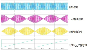
Figure 1. Correspondence between resolver signals
1. Resolver "hardware decoding": resolver-digital conversion chip RDC
The conventional decoding scheme is to use the resolver-digital conversion chip RDC and the rotary The transformer sensor is directly connected, as shown in Figure 2, the analog signals (sine and cosine signals) output by the resolver are decoded on the hardware to obtain the angular position signal and speed signal of the resolver rotor. This scheme is commonly known as " hardware decoding". Commonly used RDC chips include AD2S90, AD2S1200, AU6802/ZSZ/XSZ-014, etc.
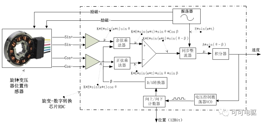
Figure 2. Resolver-digital conversion chip RDC decoding Architecture
The signal from the resolver is converted within the RDC chip into a digital value: position information, and speed is determined by counting the number of pulses within a specific time window. The RDC decoding process is shown in Figure 2. The oscillator generates an excitation voltage (about 8kHZ, 10Vrms) to supply power to the resolver position sensor, and the resolver outputs sine and cosine signals in the RDC chip through a cosine multiplier, a sine multiplier and a comparison After the device is available:
△V=K* E*sin(ω*t)*sinθ*cosβ- K* E*sin(ω*t)*cosθ*sinβ Simplified It can be seen that: △V=K* E*sin(ω*t)*sin(θ-β) Among them, β is the angle corresponding to the counter;
△V then enters the synchronous rectifier and demodulates the excitation signal, removes the carrier frequency ω, and obtains the difference voltage signal with sin(θ -β) is directly proportional, namely:
△V' =A* sin(θ-β )
△V' enters the integrator again, when there is a difference between θ and β angles, the integrator A DC voltage signal will be output, and input to the voltage controlled oscillator VCO to generate a pulse signal, and finally enter the up/down calculator. A closed-loop control system is formed by a sine/cosine multiplier, a synchronous rectifier, an integrator, a voltage-controlled oscillator, a calculator, and a D/A converter, similar to a phase-locked loop PPL. When the difference between θ and β angles is 0, the digital value of the counter corresponds to the angle analog output from the resolver position sensor, and the decoding of the RDC chip is completed.
During the continuous rotation of the resolver, the VCO generates pulses until the count value of the counter corresponds to the analog value of the rotor angle at the time of input, that is, the offset of the resolver rotor angle. At the same time, the voltage controlled oscillator The frequency of the resolver is proportional to the rotational speed of the rotor, so the output voltage of the integrator can be output as a speed signal.
**2. ****Resolver "software decoding": **Digital signal processing and software technology
Current new energy vehicle electric drive Resolver decoding mostly adopts the combination of CPU processor, FPGA/CPLD and software technology. Compared with resolver-digital conversion chip RDC decoding, it is mainly based on the following points:
Meet functional safety requirements ASIC;
Reduce cost, cancel RDC chip;
Eliminate the lag effect of speed , using digital filters, using software to achieve bandwidth conversion, to compromise the relationship between bandwidth and resolution, and make bandwidth a function of speed;
Improve the anti-environmental noise
The following will take a digital processor resolver software decoding architecture based on meeting functional safety requirements as an example to introduce resolver "software decoding", as shown in Figure 3. The resolver output sin+/-, cos+/- signals are processed by a "comparator" to obtain a single-ended sin/cos signal, enter the low-pass filter, and then carry out AD conversion and send them to FPGA and CPU respectively.
FPGA will generate the excitation voltage signal of the resolver, and process the sin/cos signal to calculate the angle and speed of the rotor; at the same time, the CPU will also process the sin/cos signal to calculate the rotor angle and speed, and calculate the result with FPGA In addition, the CPU will also monitor the processing process of the input/output signal of the resolver by the FPGA.
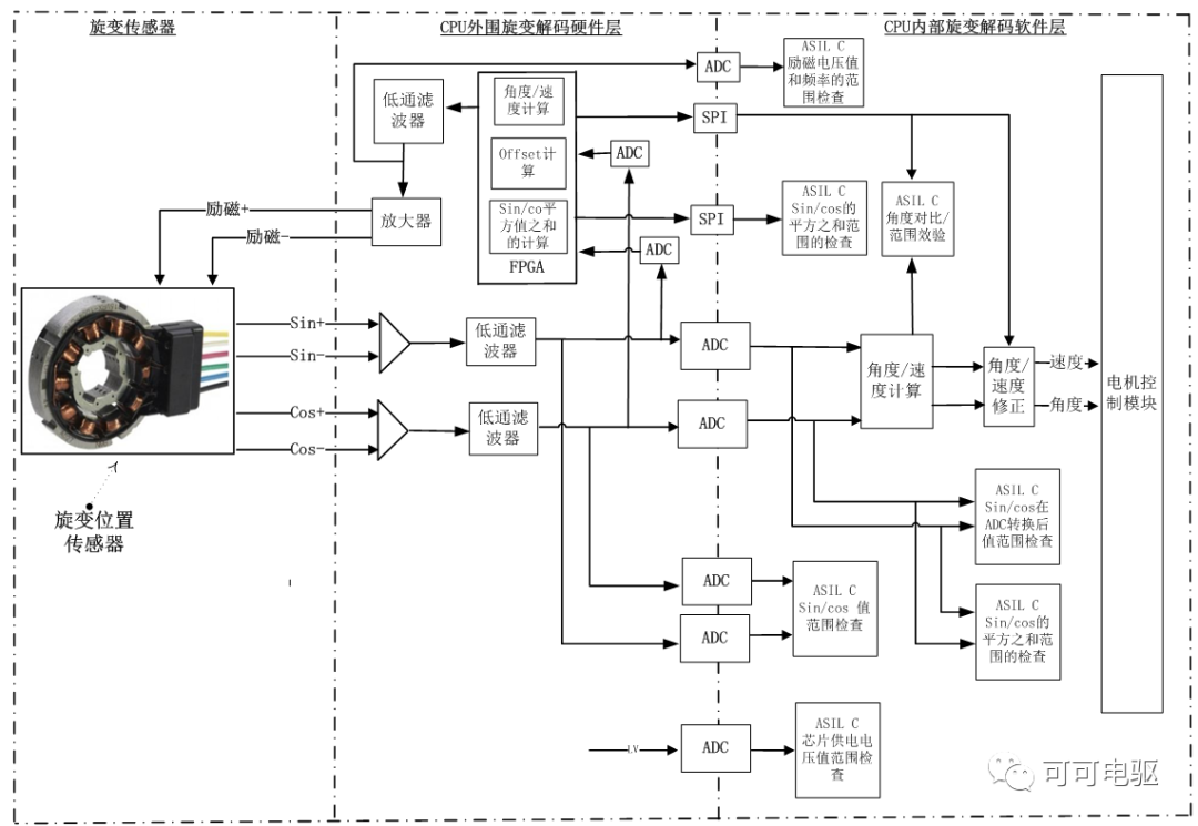
Figure 3. Digital processor resolver software decoding architecture
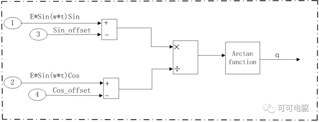
Using the Luenberger observer to calculate the rotor position angle is shown in Figure 4:
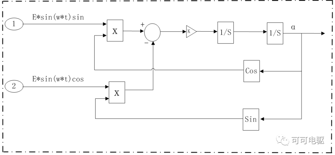
Figure 4. Luenberger observer calculation angle
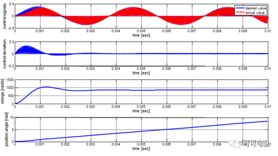
Figure 5. The signal correspondence of the angle calculated by the Luenberge observer
The rotor angle is calculated by the arctangent algorithm, as shown in Figure 6, using The rotor position angle calculated by the Luenberger observer is compared and verified.