-
Mail us
sale@tiger-transformer.com -
Phone us
(+86)15155183777 -


Mail us
sale@tiger-transformer.comPhone us
(+86)15155183777
The sine wave oscillator is a device that uses its own circuit to automatically convert DC power into AC signals of specific frequency and amplitude without the need for external signal excitation. Sine wave oscillators are widely used in various electronic devices, such as carrier signal sources in wireless transmitters.
Sine wave oscillators can be divided into two categories according to their working principles: feedback oscillators and negative resistance oscillators. Feedback oscillators add positive feedback to the amplifier circuit. When the positive feedback is large enough , the amplifier produces oscillation and is currently the most widely used type of oscillator. The negative resistance oscillator directly connects an active device with negative resistance characteristics to the resonant circuit to produce constant amplitude oscillation.
LC sine wave oscillator testing and simulation
Feedback oscillators that use LC resonant circuits as frequency selection networks are called LC sine wave oscillators. Commonly used circuits include three-point oscillators. oscillator and transformer feedback oscillator.
1. Testing and simulation of capacitive three-point oscillator
The capacitive three-point oscillator is also called the Colpitts oscillator. The output frequency of this oscillator is stable and The waveform is better.
The simulation of the capacitor three-point common emitter oscillator is shown in Figure 8-30.
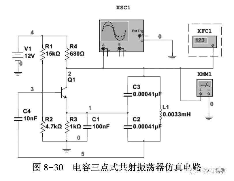
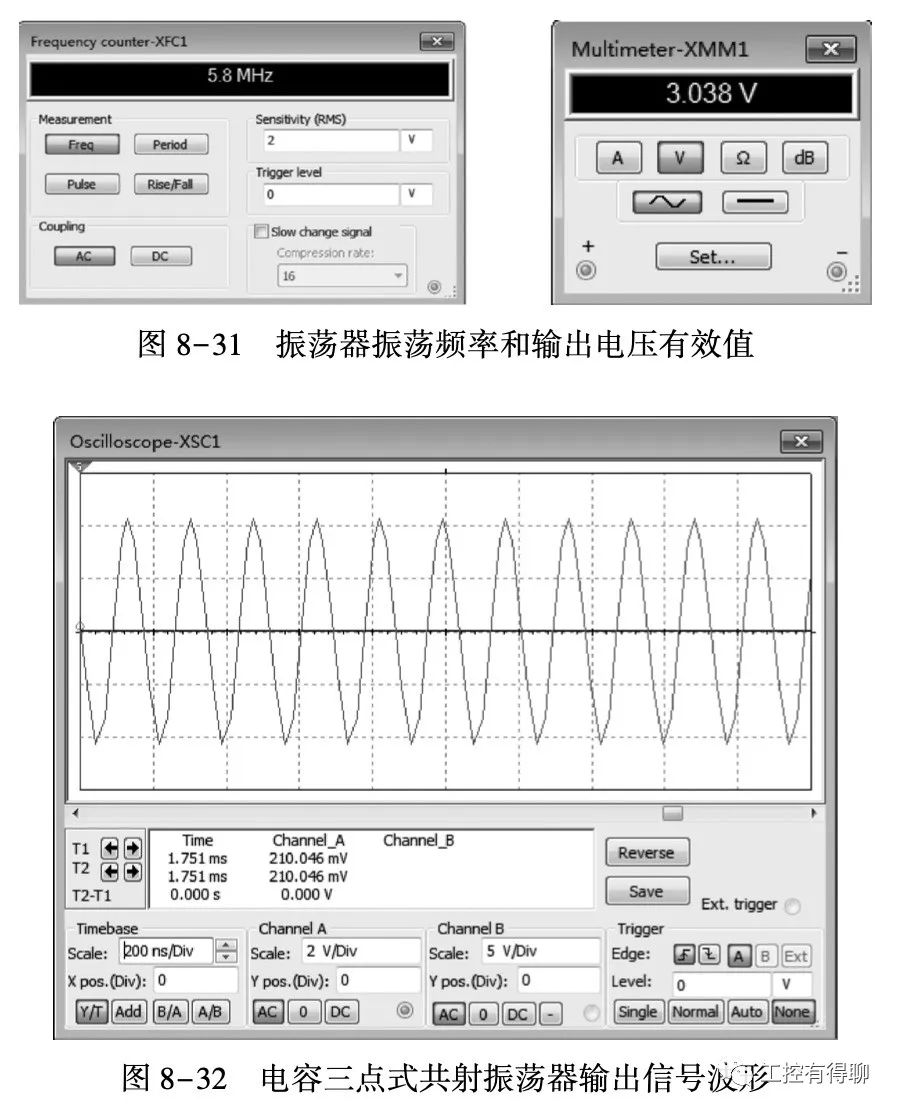
Simulation operation, output signal frequency is 5.8 MHz, and the effective voltage value of the output signal is 3.038V, as shown in Figure 8-31. The oscillator output signal waveform is shown in Figure 8-32.
2) The simulation of capacitor three-point common base oscillator is shown in the figure As shown in Figure 8-33, the simulation output is shown in Figure 8-34.
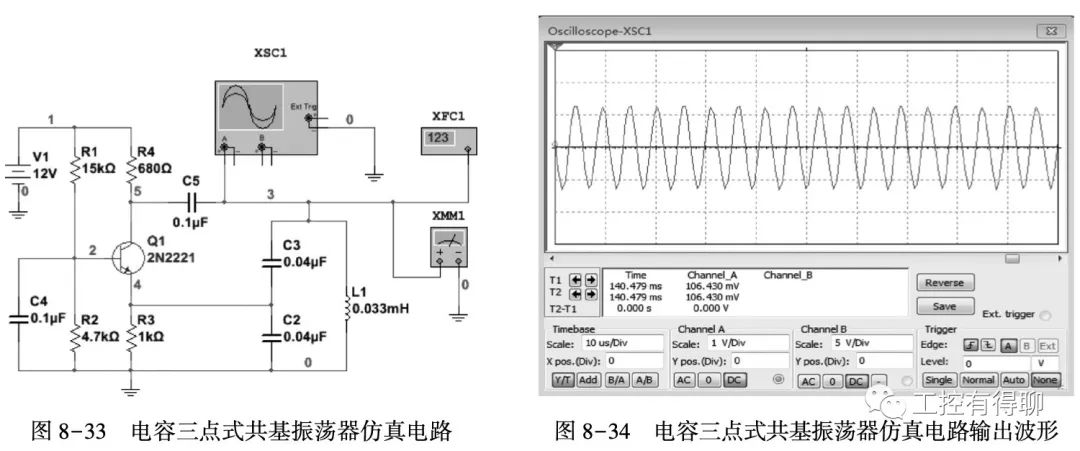
When the operating frequency is high, the capacitor three-point common base Compared with the common-emitter oscillator, the oscillator is easier to start.
2. Testing and simulation of improved capacitor three-point oscillator
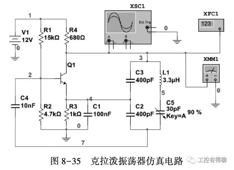
(1) Testing and simulation of Klap oscillator
Krad The splash oscillator is an improved capacitor three-point oscillator, as shown in Figure 8-35. This type of oscillator adds an adjustable capacitor C5 to the LC resonant circuit of the original capacitor three-point oscillator. As long as L1 and C5 are connected in series, the Equivalent to an inductor, this oscillator is still a capacitive three-point oscillator. The advantage of this circuit is high frequency stability.
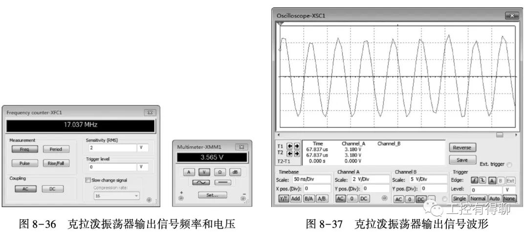
The simulation runs and the output signal frequency is 17.037 MHz. , the effective voltage value of the output voltage is 3.565 V, as shown in Figure 8-36. The oscilloscope output signal waveform is shown in Figure 8-37.
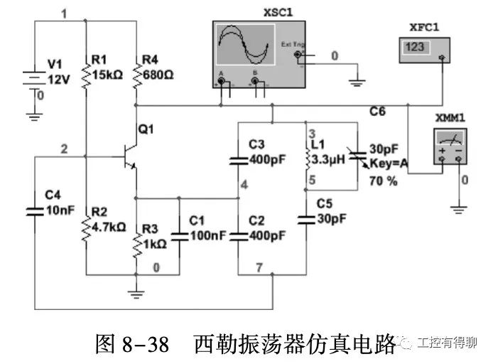
(2) Siller Oscillator Testing and Simulation< /p>
The Schiller oscillator is a capacitive three-point oscillator improved on the Clapp oscillator, as shown in Figure 8-38. This type of oscillator adds an adjustable capacitor C6 in parallel with the inductor in the LC resonant circuit of the Clapp oscillator. This circuit also has the advantages of stable frequency and high accuracy.
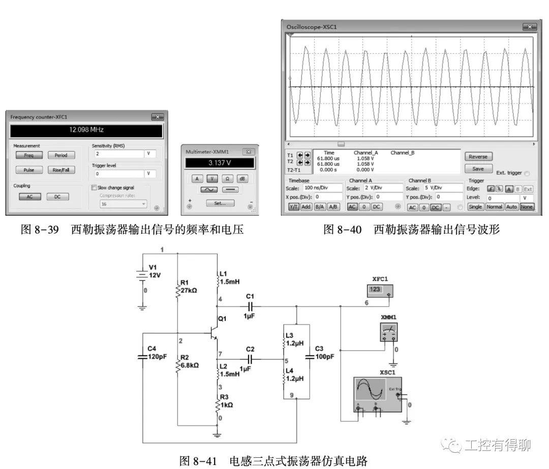
When the simulation is run, the frequency of the output signal is 12.098 MHz; the effective value of the output voltage is 3.137 V, as shown in Figure 8-39. The output signal waveform is shown in Figure 8-40.
3. Inductive three-point oscillator test and Simulation
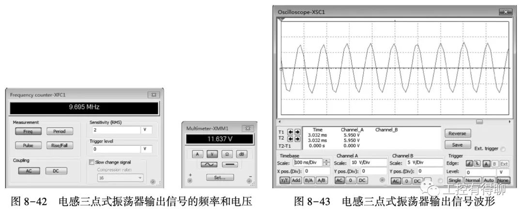
The inductor three-point oscillator is also called the Hartley oscillator, as shown in Figure 8-41.
Run the simulation, the frequency of the output signal is 9.695 MHz, The effective value of the voltage is 11.637 V, as shown in Figure 8-42.
The oscilloscope displays the oscillator output signal waveform as shown in Figure 8-43.
4. Transformer feedback oscillator test and Simulation
The transformer feedback oscillator can be divided into three types of circuits according to the different positions of the oscillation circuit connected to the collector, base and emitter of the transistor, namely, the collection circuit and the base circuit. type circuit and modulation type circuit.
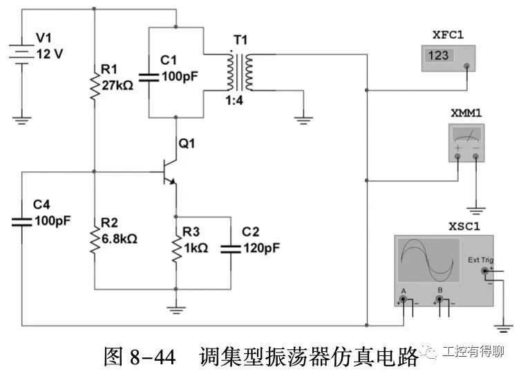
The simulation circuit of the collective oscillator is shown in Figure 8-44. The oscillator is composed of a transistor and an LC resonant circuit to form a frequency-selective amplifier. The transformer feeds back the output signal of the amplifier to the amplifier input terminal to obtain an appropriate amount of positive feedback to achieve self-excited oscillation.
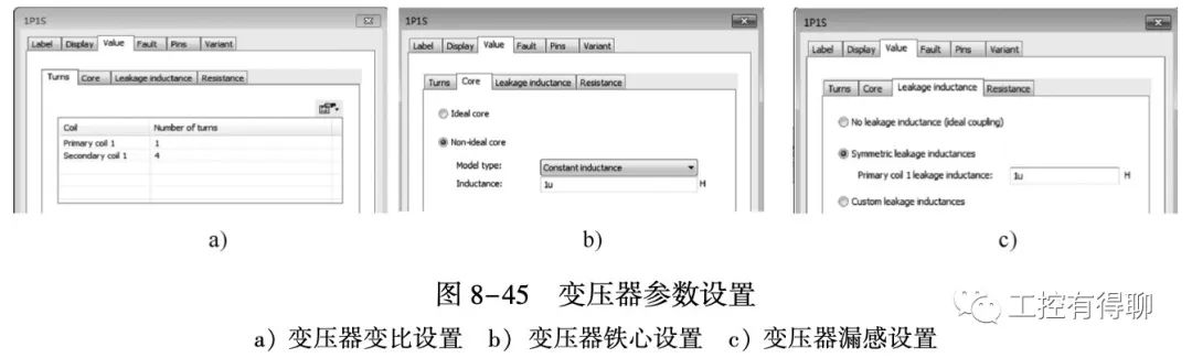
Be careful to modify the parameters of the transformer before testing, double-click the transformer The transformer parameter window pops up, as shown in Figure 8-45. Click "Value" → "Turns" to modify the ratio to 1:4, as shown in Figure 8-45a; switch to the "Core" tab, select the "Non-idealcore" radio button, and modify the Constantinductance value to 1μH, As shown in Figure 8-45b; switch to the "Leakage inductance" tab, select the "Symmetric leakage inductances" radio button, and modify the value to 1μH, as shown in Figure 8-45c.
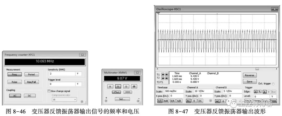
The simulation runs, and the frequency meter displays the oscillator output signal. The frequency is 10.093MHz, and the effective value of the output voltage is 9.87V, as shown in Figure 8-46. The oscilloscope displays the oscillator output waveform as shown in Figure 8-47.