-
Mail us
sale@tiger-transformer.com -
Phone us
(+86)15155183777 -


Mail us
sale@tiger-transformer.comPhone us
(+86)15155183777
This is the physical picture and circuit symbol of the diode:
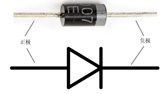
Diode
The small gray stripe at the end of the diode indicates the cathode of the diode.
What is a diode?
A diode is a device that only allows current to flow in one direction.
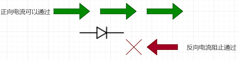
Only allow one-way flow
So if you feed AC into the positive terminal of the diode, the negative voltage will be blocked and you will only get the positive half of the waveform at the negative terminal of the diode. This process is called half wave rectification (Half Wave Rectification). It is also suitable for other waveforms with negative voltage, such as: square wave, triangle wave, etc.
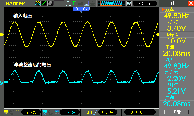
Sine wave half wave rectification
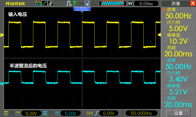
Square wave half wave rectification
Triangle wave half wave rectification
If you look carefully For the rectified waveform of the sine wave, you will find that there is a missing piece at the top of the waveform:
One piece is missing
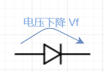
That's because perfect diodes don't exist. All diodes have a so-called forward voltage drop (Voltage drop or Vf). This means that every time current flows forward through the diode, the voltage typically drops by around 0.7 volts. The exact number will vary with temperature, current and diode type, but for now let's take it at 0.7 volts.
Forward Voltage Drop
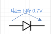
Therefore , the diode will not conduct until the voltage across it reaches 0.7 volts.
Once turned on, there is always a 0.7 volt drop across it.
0.7 Volt Drop
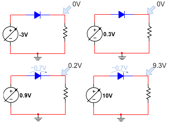
For For a diode, when the input voltage is negative, the diode cannot conduct, so the output voltage is 0 volts.
When the input voltage is 0.3 volts, it is still not enough to make the diode conduct, so the output voltage is 0 volts.
When the input voltage is 0.9 volts, the diode conducts, but due to the forward voltage drop, the voltage at the output is 0.2 volts.
When the input voltage is 10 volts, the output voltage is 9.3 volts.
Only when it is higher than 0.7 volts
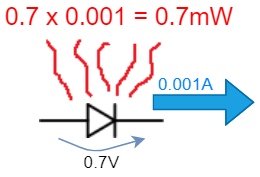
The diode also has a more important parameter, the rated power. The power of a diode is calculated by multiplying Vf by the current through the diode.

Diode power calculation formula
So At 1mA, only 0.7mW is lost as heat, not a big deal.
0.7mW
But when passed At 3 amps the diode will generate 2.1 watts of heat, which is a lot. So you either use a more powerful diode, or a diode with a lower forward voltage drop, such as a Schottky diode.
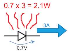
2.1W
The last parameter worth noting about diodes is: switching speed. In the document, this parameter is generally written as Reverse Recovery Time in the electrical parameters (ELECTRICAL CHARACTERISTICS), and the symbol is: trr.
1N4007 is designed for low frequency power electronics, such as 50-60 Hz AC mains in the home.
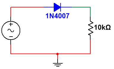
Diode Speed Test Circuit
Frequency At 50 Hz, everything is fine:
When the frequency of the AC signal increases to 10 kilohertz, the diode starts to fail because it starts to conduct in reverse:
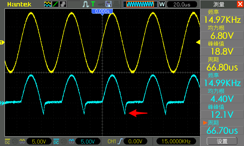
1N4007 is finished at a dozen kHz
This is because the diode is allowing current It takes time to switch between forward conduction and blocking reverse current. Different diodes have different switching speeds.
The switching speed of 1N4148 is: 4ns:
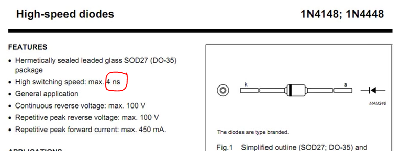
The switching speed of 1N4148 reaches 4 nanoseconds
Replacing the above 1N4007 with 1N4148, it can support signals with a frequency of 100k Hz.
1N4148 can support signals up to 100 kHz
For RF applications, you will need faster switching diodes.
When you design a circuit, you need to consider the diode's maximum rated voltage, forward voltage drop, rated current, and switching speed.
Several important parameters of the diode
With the above knowledge, you can build something with diodes. The most common use of diodes is to convert alternating current to direct current. Next we build an unregulated (unregulated) DC power supply.
First we need to step down the domestic 220 volt mains to a lower, safer AC.
At zero load, the transformer outputs a clean sine wave, about 36 volts peak-to-peak, with a frequency of 50 Hz.
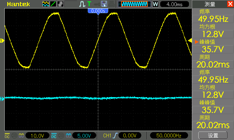
clean sine wave
Add a 1N4007 diode behind the output waveform, and then measure the voltage across the diode. You can see from the waveform that the negative voltage is cut off.
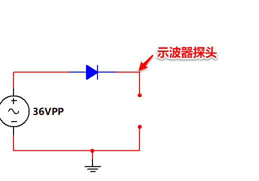
Single diode rectifier circuit
Below It is the single diode rectification waveform above:
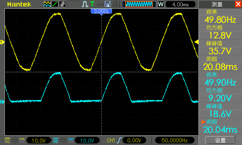
Single diode rectification waveform
The following is the effect of superimposing the above two waveforms together:
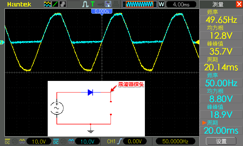
Single Diode Rectification Waveform
Technically, I use only one diode to convert AC to DC because the negative voltage is eliminated. But this DC is really bad, half the time is a weird hump voltage, half the time the voltage is zero, basically useless. To make it useful, we need to add a little stability to it. Speaking of voltage regulation, it's time to bring in our old friend the capacitor. We add a capacitor at the output to stabilize the voltage.
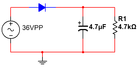
We add a 4.7 microfarad capacitor after the diode, and immediately output a perfect voltage of 18 volts DC:
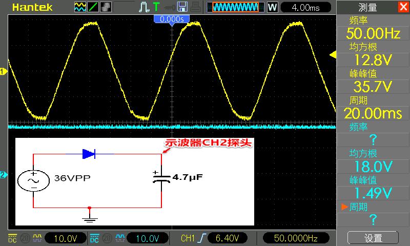
18V DC
Everything looks so good, that's because there is no Add load. The capacitor is charged through the diode, and since there is no load, the charge stored in the capacitor is not depleted. Let's load the circuit with a 4.7k resistor and see what happens.
4.7k load
Through ohms The law calculates that the circuit through the load is approximately 4 mA, 18 volts / 4.7k = 4 mA.
The CH1 probe is still connected to the positive pole of the diode, and the CH2 probe is still connected to the negative pole of the diode. In the figure below, CH1 is yellow and CH2 is blue.
It’s embarrassing
The 4mA current circuit can no longer support it, and the output DC power becomes a jagged and violently jittering waveform. As can be seen from the above waveforms, when the AC input is positive, the diode allows current to pass and thus the capacitor charges. But once the input voltage drops to zero, the diode prevents the reverse flow of current, and the only source of energy left is that tiny 4.7 microfarad capacitor. As the picture shows, it drains quickly even under light load.
How to solve this problem? If we think of the capacitor as a reservoir for storing charge, we can increase the capacity of the reservoir to provide enough power for the load until the next time the input voltage becomes positive again.
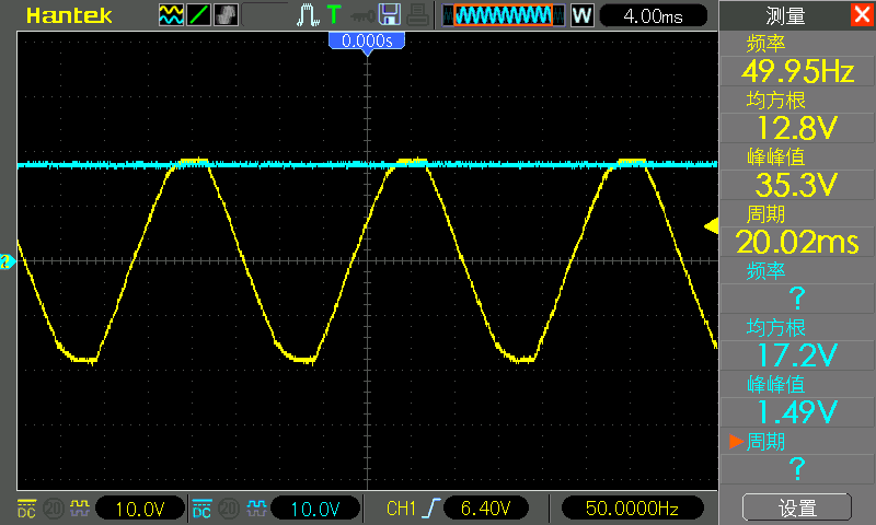
Let's replace that tiny 1 microfarad capacitor with a larger 470 microfarad capacitor and see what happens.
After increasing the capacitance to 470 microfarads, the DC is straight again, which looks fine. Now we have a DC source that can deliver a few mA, which is enough to power some sensors and op amps.
Looks good
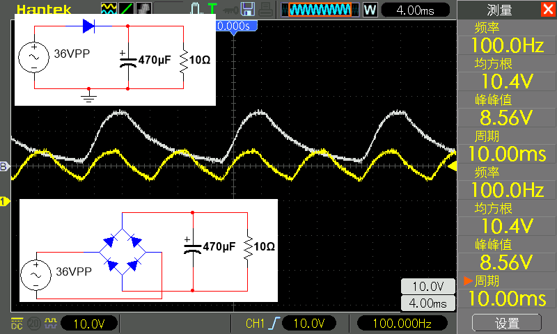
Now , let's increase the load a bit. We increased the load resistance to 10 ohms, which increased the current demand of the circuit to over an amp.
10 ohm load waveform
output The voltage jittered again, and the amplitude of the voltage ripple was very large. The rms voltage is only 8 volts, so only about 0.8 amps flow through the circuit.
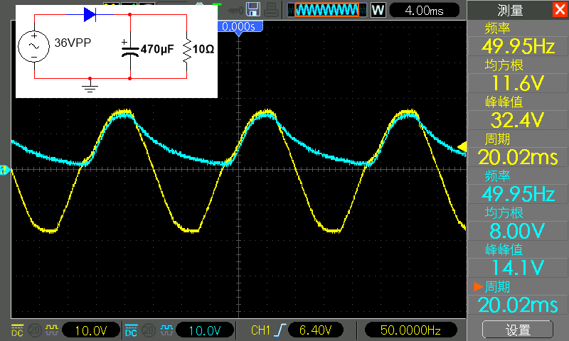
So, even 470 microfarads is not enough. We can add more capacitors.
3290uF capacitor waveform
much better , now the rms voltage has reached 10 volts, indicating that the current flowing in the circuit is about 1 ampere, and the peak-to-peak value has dropped from 14 volts to more than 5 volts. But the 5 volt ripple is also really too big. We can continue to add more capacitors to reduce the ripple, but if the load current continues to increase, reaching several amperes, then we have to continue to increase capacitors.
Let's take a look at the following magical circuit:
Bridge rectifier
It is composed of four diodes arranged in a certain order, which is the "bridge rectifier" circuit. Also known as a bridge rectifier.
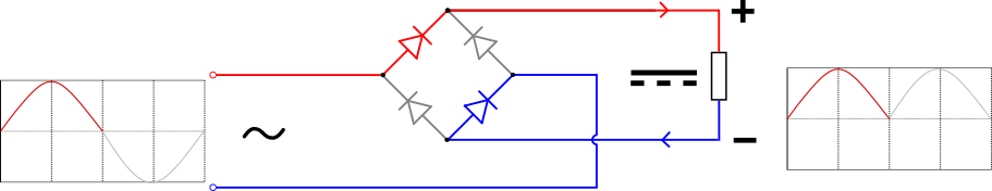
Positive Half Week
During the positive half cycle of the sine wave, the voltage connected to the left of the diamond is positive (red), and the voltage connected to the right of the sporadic is negative (blue). The red and blue diodes conduct, allowing current to flow in the forward direction. The remaining two diodes are cut off, preventing flow through, which is equivalent to an open circuit. Current flows from the upper terminal to the right along the red (positive) path to the load, along the load to the output, and back to the lower supply terminal along the blue (negative) path.
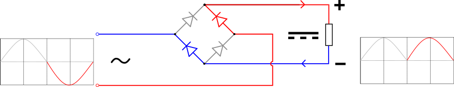
Negative half cycle
Now in the second half of the sine wave, the input connected to the left of the diamond is negative (blue), the input connected to the right of the diamond is positive (red), and the current flows from the lower terminal along the red (positive) The path flows right to the output, returning along the blue (negative) path back to the power terminal below.
So instead of half wave rectification cutting off the negative half cycle of the AC and not using it, full wave rectification inverts the negative half cycle and uses it. So you get 100 Hz DC at the output instead of 50 Hz.
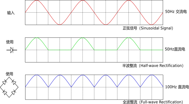
Half full-wave rectification comparison
Just like when using a diode for half-wave rectification, we can also use capacitors to filter the output of full-wave rectification to obtain a smoother voltage.
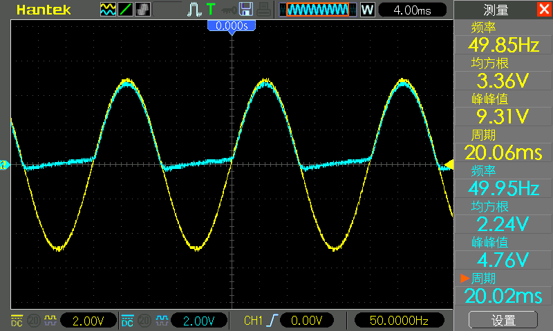
This is a bridge finisher built by the author using four 1N4007 diodes, inputting the 12V output of the transformer, note that I used a 4.7k resistor as the load. Because there is no capacitor filtering at this time, if the output waveform is directly measured without connecting to the load, there will be deformation:
From the waveform below, you can see that the previous 50 Hz voltage has positive and negative voltages, after After rectification, it becomes a constant positive hump voltage of 100 Hz without negative voltage. This is called full wave rectification because we are rectifying a full AC wave. The white waveform is the input waveform, which is saved and displayed using the Reference Waveform function of the oscilloscope. Because there is no common ground for AC and DC at this point, it is not possible to measure both waveforms simultaneously. The rectified waveform has a peak-to-peak value of 16.3 volts and an rms value of 11.2 volts.
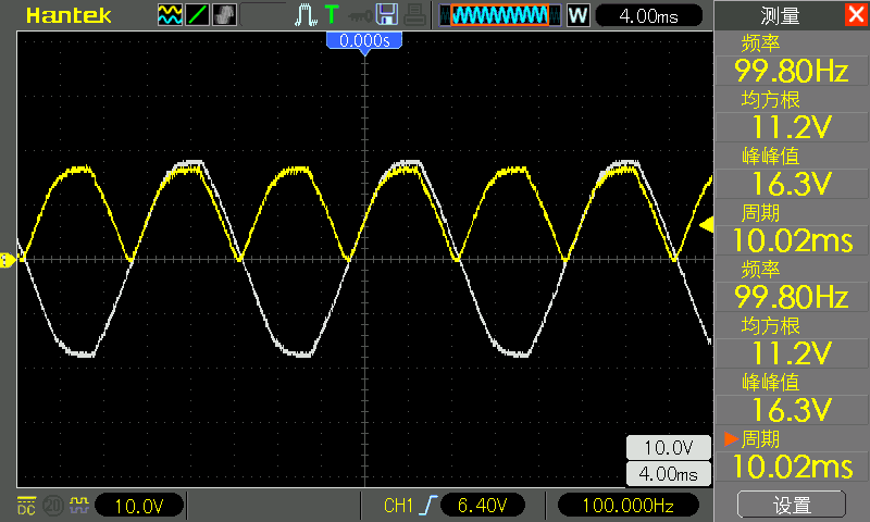
Rectifier bridge waveform
Now let Let's use a 470 microfarad capacitor into a 10 ohm load to see how full wave rectification performs.
Comparison of full-wave rectification and half-wave rectification
Now we get an average voltage of 10 volts instead of the 8 volts we got earlier with a single diode. This is because a full wave rectifier charges the capacitor twice as fast as a half wave rectifier. Because we make full use of the positive and negative two half-waves of the 50 Hz AC mains.
Now think about what a difference those extra diodes cost for only a few cents.
The bridge rectifier may be a bit difficult to understand, because this circuit is too classic, but it is really one of the best expressions of human wisdom, and its figure is everywhere, so it is necessary to learn it.
Now let's look at the full-wave rectified waveform filtered with a 3290 microfarad capacitor:
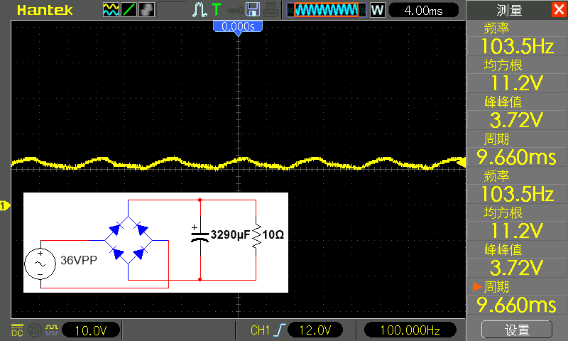
The rectification uses a 3290uF capacitor
The root mean square value (which can be understood as the average value) reaches a voltage of 11.2 volts, which is higher than the 10 of the 470 microfarad filter used before volts, the power supply ripple is also reduced from 8.5 volts to 3.72 volts.
In other words, a bridge rectifier combined with a large number of capacitors can turn almost any high-current alternating current into high-current direct current. However, it should be noted that the rated voltage of the diode and capacitor used must be greater than the peak voltage of the rectified waveform. Here, the peak-to-peak value of the waveform after full-wave rectification is 16.3 volts, and a capacitor with a rated voltage of 25 volts or above is sufficient.
One thing to note, these are unregulated DC power supplies. This means that even though we've managed to smooth out a lot of the voltage ripple, we'll still have problems with the average voltage variation under load.
16.4 volts at no load:
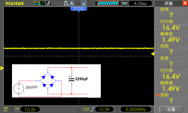
No-load voltage is stable
The voltage drops to 11.2 volts at 1 amp load:
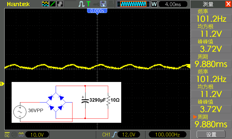
The voltage drops when the load is on
If the current in the circuit continues to increase, the output voltage will drop. For some circuits with wide voltage requirements, this is not a problem. But for microcontrollers and some other digital electronics, they need a very precise voltage source, for which a so-called regulated power supply is generated.
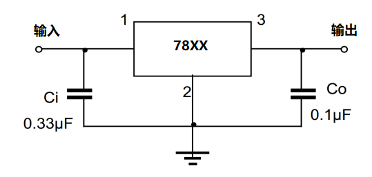
Linear regulator typical circuit