-
Mail us
sale@tiger-transformer.com -
Phone us
(+86)15155183777 -


Mail us
sale@tiger-transformer.comPhone us
(+86)15155183777
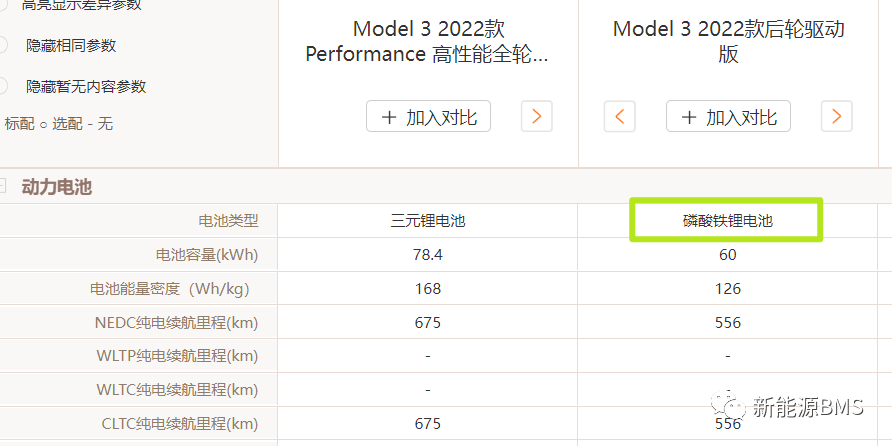
In the domestic rear-drive version of MODEL 3, the CATL lithium iron phosphate battery is used. The BMS acquisition board on the battery pack is of a different design than before. Let’s learn together today.
Ningde The ferroelectric core module version of MODEL 3 has 4 acquisition boards on a battery pack. You will find that it is very different from the acquisition boards of cylindrical cells analyzed before, regardless of size, AFE, connection method, etc. are different, which will be analyzed in detail below.
The sampling plate shell is made of plastic material, divided into upper and lower shells, which are black,
The upper and lower shells on the back of the sampling plate It appears to be snap-fitted to the PCB.
Remove the lower case, revealing the B side of the PCBA, and you can see that the buckle of the upper case passes through the PCB and is fixed with the lower case.
Next turn to PCBA, the size of the entire PCBA is about 232mm*65mm*15mm, the thickness of the PCB is 1.6mm, it is green, and it is a four-layer board;
The minimum package of the T surface device is 0603, all devices are coated with conformal paint, the PCB surface treatment method is ENIG, the via holes are not filled with green oil, and the solder mask is open.
On the B side of the PCBA, it can be found that there are no devices or test points arranged on the B side, but the conformal paint is still coated.
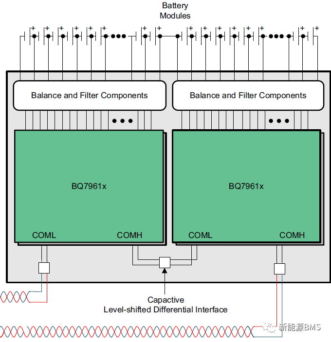
Let’s take a brief look at the circuit scheme of the sampling board. The basic function distribution of the entire board is shown in the figure below. The circuits are similar, and there are two AFEs on one board. The circuit is capacitive isolation communication inside the board, and transformer isolation communication externally.
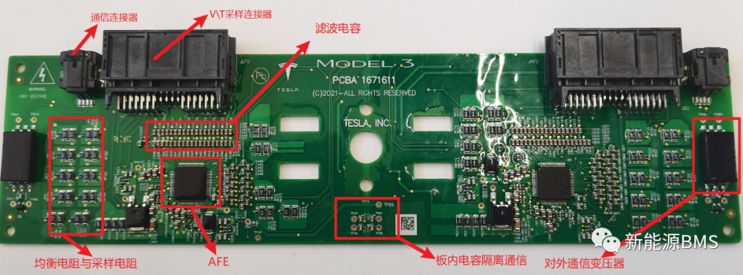
AFE I chose TI's BQ79616, which is different from the MODEL 3 sampling board I saw before. The AFE analyzed before was Robin and Batman customized by Tesla, but this version uses the existing mature model. The entire single board The communication topology architecture is as follows (from TI official website).
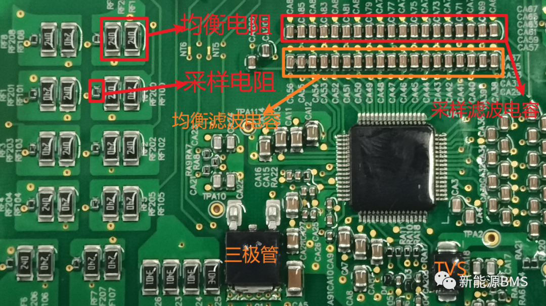
Sampling The equalization and communication circuits are basically in accordance with the scheme recommended by the original TI factory, as shown in the figure below: the sampling input adopts RC filter, the capacitor is in the form of differential mode, and is arranged on the adjacent voltage sampling pin; the equalization adopts the internal equalization scheme, and in Place differential-mode capacitors adjacent to the balance pin.
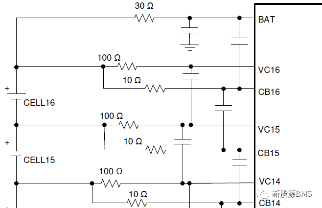
corresponding The circuit is shown in the figure below, the sampling input resistance is 100Ω/0603 package, and the sampling filter capacitor adopts two series schemes; the equalizing resistor adopts two 24Ω/1206 resistors in parallel, and the capacitor at the equalizing pin is also in the form of two series ; The daisy chain communication circuit will not be introduced in detail, you can check the specification of the chip.
Finally Another place to look at is the connector for cell voltage and temperature sampling. The board end is in-line package, which comes from TE. It seems that there is no special place.
But the end of its plug-in line is an FPC connector, as shown in the figure below (picture from TE): Our common FPC connector is board-to-board, only one side is connected to the PCB, and the other side is connected FPC, and the FPC and the connector are generally fixed by welding; but this FPC connector is different, it is connected to the FPC using terminal blocks, and the battery pack of this version of MODEL 3 adopts this solution.
Further, the FPC was taken out from the connector, and the wiring terminals inside were exposed. It was found that the connection between the terminals and the FPC was a piercing contact connection, and the wiring terminals were in direct contact with the copper inside the FPC.
Looking at the other side, there is glue coating for protection where the terminal block contacts the PFC.
Review editor: Liu Qing