-
Mail us
sale@tiger-transformer.com -
Phone us
(+86)15155183777 -


Mail us
sale@tiger-transformer.comPhone us
(+86)15155183777
1. Direct start of squirrel cage motor
1. Contactor self-locking and overload protection
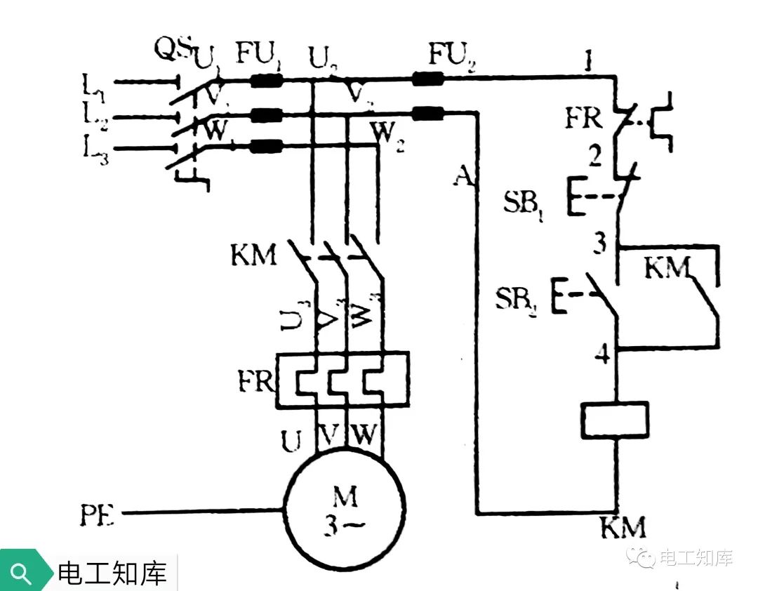
1)Close the power switch QS, press the start button SB2, the AC contactor KM is energized, its main contact is closed, the power is turned on, and the motor starts.
2) Release the start button SB2, the control circuit is self-locked through the normally open auxiliary contact KM of the contactor. Press the stop button SB1, the motor stops running.
3) FU1 and FU2 are circuit short circuit protection, thermal relay FR is motor overload protection.
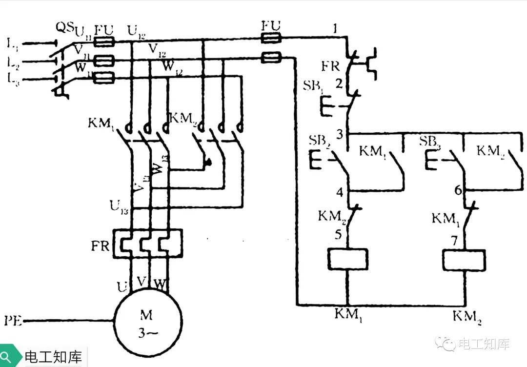
2. Contactor interlock forward and reverse
 1)
1)
Close the power switch QS, press the forward rotation start button SB2, the contactor KM1 will be electrically activated and self-locked, and the motor will rotate forward.
2) Press the stop button SB1, and the forward rotation control loop is disconnected. Press the reverse start button SB3, the contactor KM2 will be electrically activated and self-locked, and the motor will run in reverse.
3) In order to ensure that the KM1 and KM2 coils of the contactor will not be energized at the same time, the normally closed auxiliary contacts of KM1 and KM2 are respectively connected in series in the other coil circuit for interlocking.
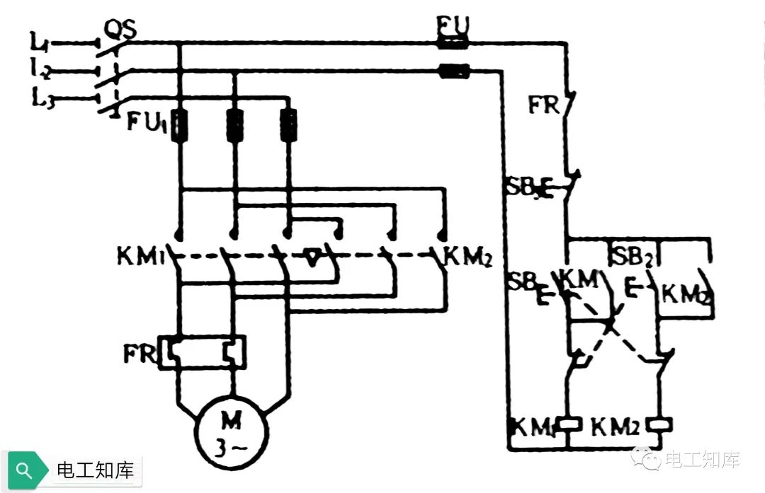
3. Button interlock forward and reverse
 1)< /p>
The action characteristics of the composite buttons SB1 and SB2 are break first and then close, which ensures that the main contacts KM1 and KM2 of the forward and reverse contactors will not be short-circuited due to simultaneous closing.
2) It should be noted that when the forward rotation contactor fails and its main contact is fused and cannot be disengaged, directly operating the reverse start button SB2 for reversing will cause a two-phase short circuit accident.
4. Double interlock forward and reverse
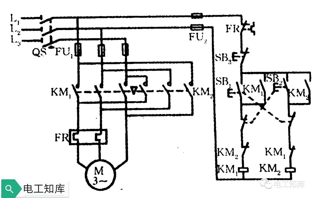
The double interlock forward and reverse control circuit has both the normally closed contact interlock of the contactor and the normally closed contact interlock of the composite button. Instead of pressing the stop button, directly press the forward and reverse button to change direction, which can also avoid the short-circuit fault of the power supply, and the operation is convenient and the safety is improved at the same time.
Second, squirrel cage motor step-down start
1, manual control string resistor step-down start
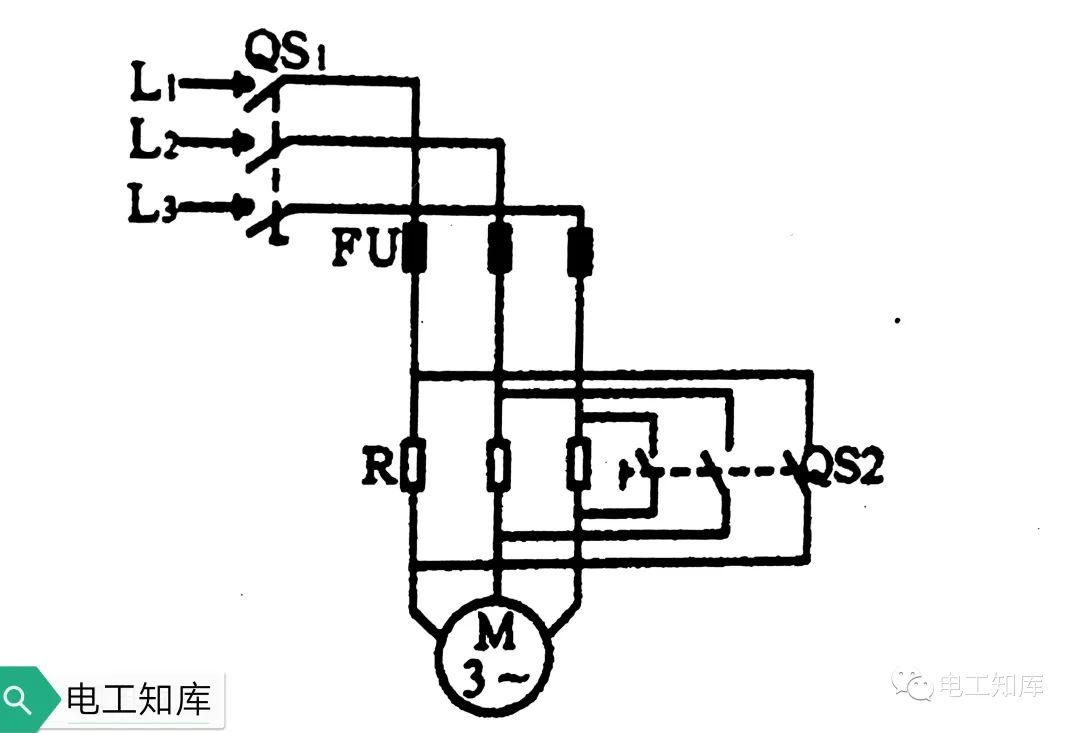
1) Turn on the power switch QS1, and the motor will be connected to the power supply through a series resistance to step down and start.
2) When the motor speed reaches a certain value, close the switch QS2 to short-circuit the series resistance R, so that the motor can run normally under the rated voltage.
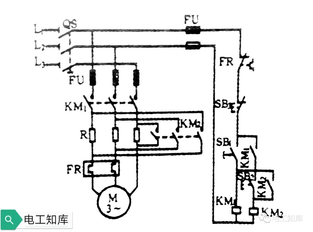
2. Contactor controls series resistance step-down start
 1 )
1 )
Close the power switch QS, press the start button SB1, the contactor KM1 is energized, the main contact of KM1 is closed, and the motor starts by stepping down the series resistance. At the same time, the KM1 normally open contact is closed and self-locking.
2) When the motor reaches a certain speed, press the button SB2, the contactor KM2 is energized, its main contact is closed, and the motor starts to run at full voltage due to the short circuit of the resistance R. KM2 normally open contacts are closed and self-locking.
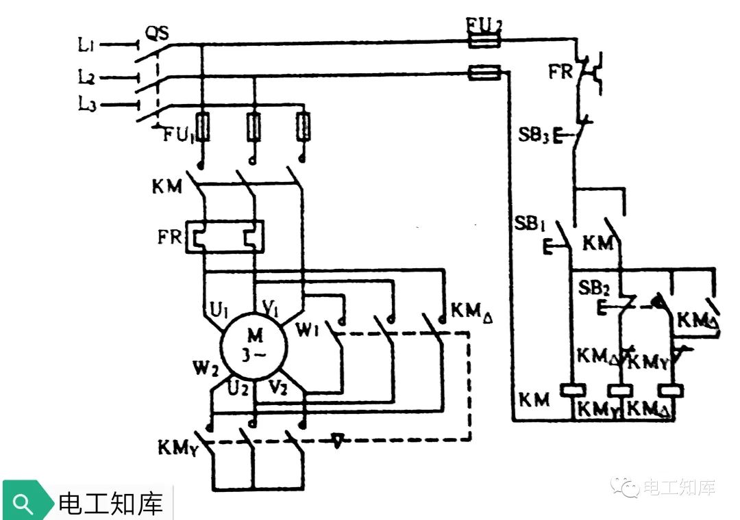
3. Contactor control Ya-△ step-down start
 1)
1)
Close the power switch QS, press the start button SB1, the contactor KM is energized, and the main contact of KM is closed. At the same time, the contactor KMya is energized, the main contact of KMya is closed, and the stator winding of the motor is connected into a star shape to start. KM normally open contacts are closed and self-locking. The KM Ya normally closed contact is disconnected for interlocking.
2) When the motor speed reaches a certain value, press the control button SB2, the contactor KM Y coil will lose power, the main contact of KM Y will be disconnected, and at the same time the contactor KM△ coil will be energized, KM△ The main contact is closed, and the stator winding of the motor is changed into a delta connection for normal operation.
3) The auxiliary contacts of the contactors KMya and KM△ are respectively connected in series in the other coil circuit for interlocking.
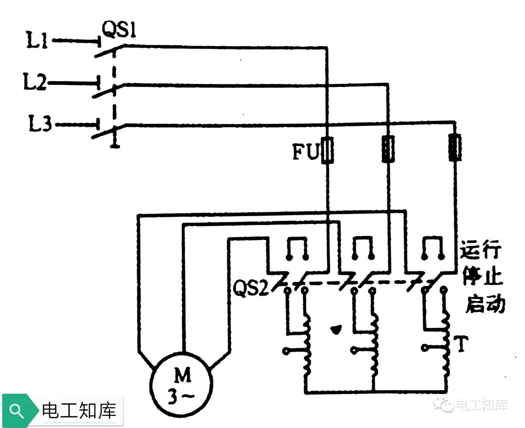
4. Manually control autotransformer step-down start
 1 )
1 )
Close the power switch QS1, and quickly turn the switch QS2 to the start position, so that the stator winding of the motor is connected with the secondary side of the autotransformer for step-down start.
2) When the motor speed reaches a certain value, turn the switch QS2 from the starting position to the running position quickly, the motor will be separated from the autotransformer, directly connected to the power supply, and run at the rated voltage.
3. Winding motor start control
1. Manual start control
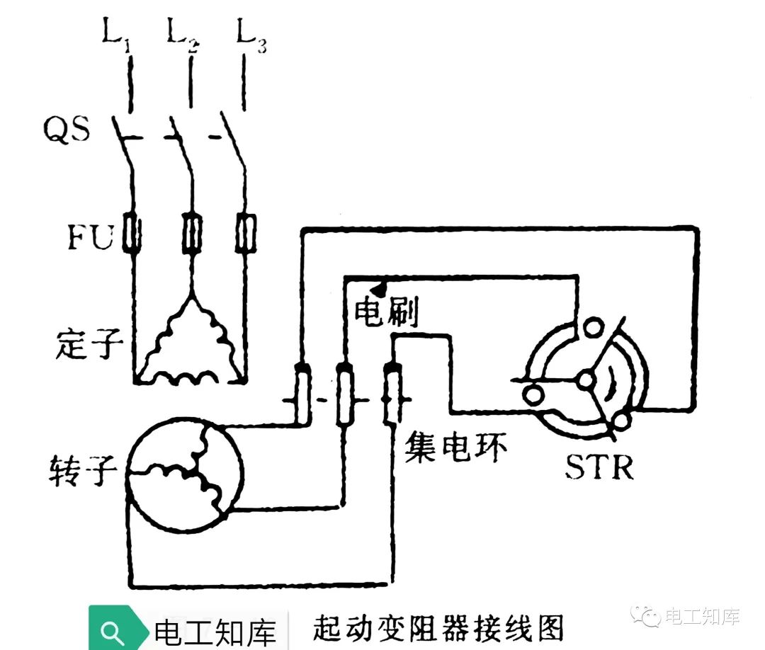
1)The starting rheostat is connected to the rotor circuit of the wound motor through the collector ring and the carbon brush. Before starting, adjust the rheostat to the maximum position so that all the resistances are connected to the rotor circuit.
2) Turn on the power switch QS, the motor starts to rotate, and gradually reduces the starting resistance as the speed increases. When all the resistance is removed, the start-up is completed, and the rotor winding is short-circuited by lifting the brush and short-circuiting the collector ring, and at the same time, the brush is separated from the collector ring to reduce the wear of the brush and the collector ring.
3) When the motor is stopped, the handle must be placed in the starting position, so that the three joints and the collector ring are disconnected, and the contact between the brush and the collector ring is restored, and all the resistance of the starting rheostat Connect to the rotor circuit for the next start.
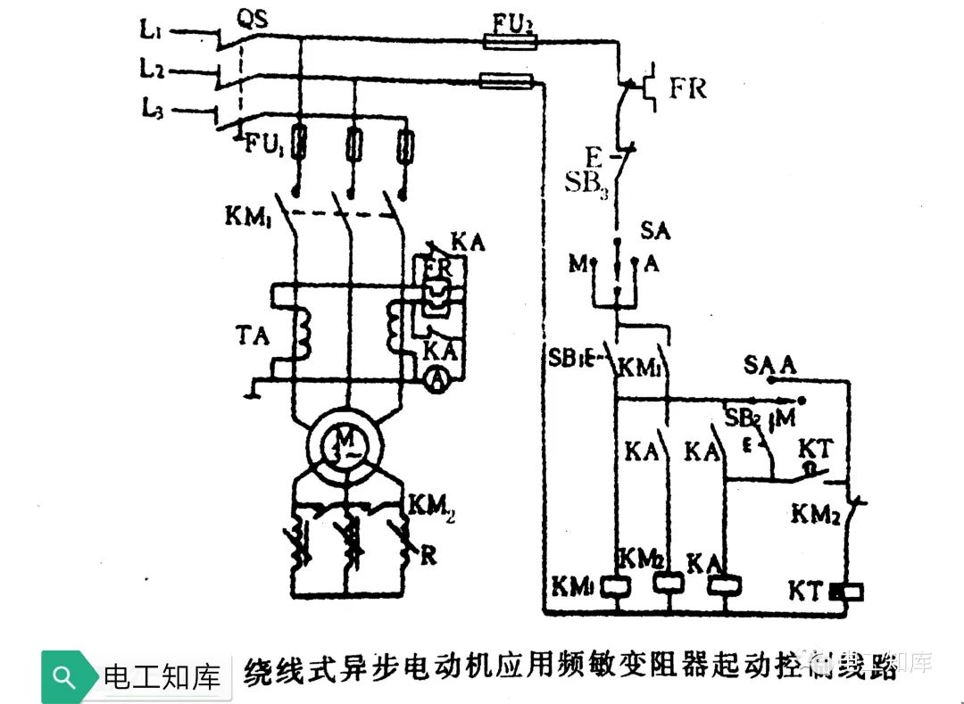
2. Frequency-sensitive rheostat start control
 1)
1)
1)
Automatic control
(1) Turn the transfer switch SA to the automatic position A, press the start button SB1, the contactor KM1 is energized and self-locked, and the motor rotor is connected to the frequency sensitive rheostat to start .
(2) When the power is turned on, the time relay KT is energized. After a set delay, the normally open delay close contact of KT is closed, and the intermediate relay KA is energized and self-locked. At the same time, the contactor KM2 is electrified, and its main contact short-circuits the frequency-sensitive rheostat, and the start-up is completed.
(3) During the start-up process, that is, the KT delay setting time, the two pairs of normally closed contacts of the intermediate relay KA short-circuit the heating element of the thermal relay FR in the main circuit. After the start-up, the intermediate relay KA is energized, and its normally closed contact is disconnected, and the heating element of the thermal relay is connected to the main circuit to work, so as to avoid a long start-up process and thermal relay overheating to cause malfunction.
2) Manual control
Turn the transfer switch SA to the manual position M, at this time the time relay KT will not work, use the button SB2 to manually control the intermediate relay KA and the contactor KM2 Actions. The starting time of the motor is determined by the interval between pressing the start button SB1 and pressing the button SB2.