-
Mail us
sale@tiger-transformer.com -
Phone us
(+86)15155183777 -


Mail us
sale@tiger-transformer.comPhone us
(+86)15155183777
Multi-rate simulation
Usually, the simulation models of power electronic control systems built in the Simulink environment are all multi-rate simulation models. This is because:
01
There are many types of models in the power electronic control system, and different models have different requirements for simulation speed.
02
For the electrical part of the controlled object model, such as permanent magnet synchronous motor and inverter, it is hoped that the simulation speed should be as fast as possible. How fast the simulation rate is specifically selected is related to factors such as the frequency of the PWM, the dead time of the inverter, and the solution method of the model. For 10kHz switching frequency, the simulation rate is preferably 100 times the switching frequency, so 1MHz (simulation step size 1µs), but if the dead time is 2µs, then the simulation step size is preferably 1/10 of the dead time (0.2 µs), at this time the simulation rate is 5MHz.
03
The mechanical part of the controlled object model, usually the simulation step size is 1ms (simulation rate 1kHz), but in the MCU HIL of the electric vehicle, in order to test the motor It is possible that the mechanical part of the motor also needs a simulation rate of more than 1MHz at this time to ensure accurate simulation of the position and speed of the motor.
04
PWM comparator model part, usually the triangular wave of PWM comparator is generated by counting with a high frequency clock. This clock is generally greater than 10MHz to ensure the adjustment accuracy of the PWM output duty cycle.
05
In the part of the controller model, the simulation rate is generally related to the switching frequency, which is an integer multiple of the switching frequency. For example, if the switching frequency is 10kHz, then the simulation rate of the controller model can be 10kHz or 20kHz. The specific choice of 10kHz or 20kHz is related to the processing capability of the DSP or Micro Controller selected in the future. In addition, in practical applications, there are cases where the switching frequency is changed, and the simulation frequency of the controller model is also changed at this time.
In short, when we build the simulation model of the power electronic control system in the Simulink environment, we need to consider the actual situation of the power electronics system, so that the simulation speed of the simulation model is consistent with the actual situation, so that the simulation results in order to accurately reflect real changes.
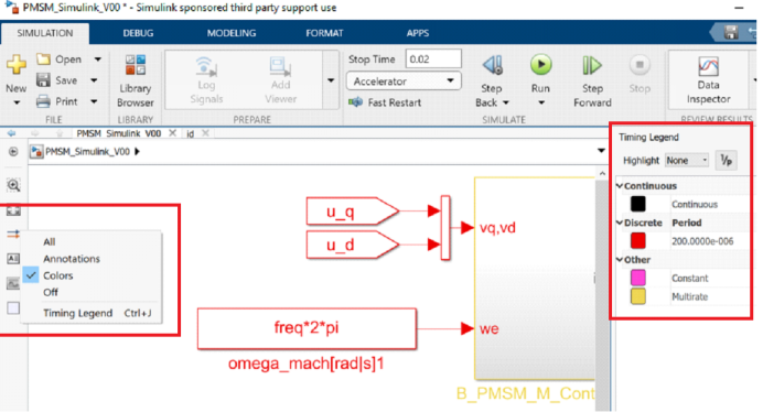
If you want to view the simulation speed of different modules in the Simulink model, you can click the icon of the model on the left side of Simulink and select Colors. As you can see from the right side of the figure below, this model has a Continuous part and a Discrete part (simulation step size 200µs). Others include Constant and Multrate (multi-rate) parts.
When building a multi-rate simulation model, different simulation rates The simulation model of Simulink is connected through the Rate Transition module of Simulink. For specific usage, please refer to the Help file of MATLAB.
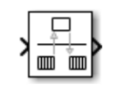
Rate Transition module< /p>
Synchronous and asynchronous
Synchronous and asynchronous are a relative concept, such as asynchronous interrupt, synchronous task, etc. So you need to figure out what is synchronous with respect to tasks and asynchronous with respect to what interrupts are. The simulation model of the permanent magnet synchronous motor control system is also used to illustrate.
The following figure shows the actual process of conventional permanent magnet synchronous motor control, including the following steps**:**
1. Sampling and holding the motor current value, ADC converts the motor current value ;
2. Read the motor speed and position values (not marked in the figure);
3. Run the motor control and SVPWM algorithm;
4. Output and update the PWM duty cycle;
The current sampling in step 1 and the update PWM duty cycle in step 4 must be completed at the same time.
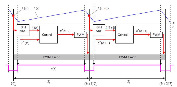
PMSM motor control process
So we can know how to regard the motor control algorithm as a task, which is asynchronous to the controlled object model. But this task is synchronous with respect to PWM-Timer.
Now that we know the actual situation of the permanent magnet synchronous motor control system, let's model it.
Permanent magnet synchronous motor control system simulation parameters
Determine the system parameters as follows:
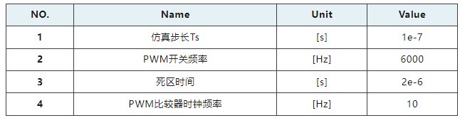
Table 1 Parameters of permanent magnet synchronous motor control system
According to PWM The switching frequency and the clock frequency of the PWM comparator can determine that the bottom point value of the triangle wave of the PWM comparator is 0, and the peak value is about 833. Therefore, the actual control cycle is determined to be 83.3µs, and the permanent magnet motor is controlled once at the position and apex of the triangle wave of the PWM comparator.
Therefore, the simulation parameters of the whole system simulation model are determined:
1. The simulation step size of the controlled object is 100ns;
2. The simulation of the PWM comparator The step size is 100ns;
3. The simulation step size of the controller is 83.3µs;
The controller simulation model is triggered to run by means of asynchronous interrupt through the PWM comparator.
Overview of the permanent magnet synchronous motor control system model
In order to ensure the synchronization of current sampling and PWM signal at each control moment, Function can be used when building the model The Call subsystem or the Enable subsystem, as shown in the figure below, at this time, the operation of the PMSM Controller is not synchronized with the time, but synchronized with the trigger output by the PWM comparator (the INT mark of the from module in the figure)
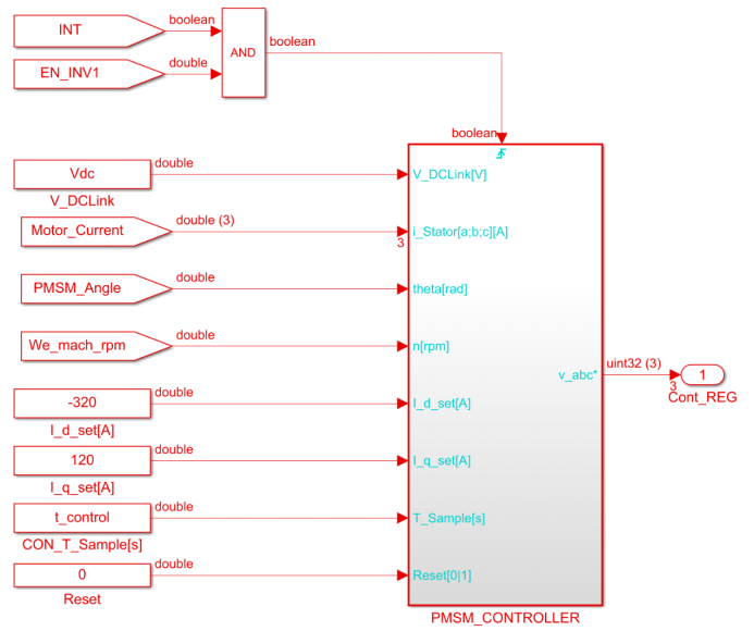
PMSM controller model based on Function Call
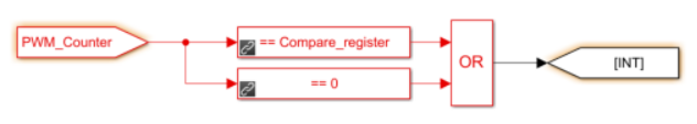
PWM comparator generates controller model trigger signal
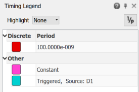
After the modeling of the entire system simulation model is completed, click the icon of the model on the left side of Simulink, select Colors, and view the simulation speed of different modules in the Simulink model. As shown in the figure below, the red color indicates that the simulation step size is 0.1µs. Pink indicates that the simulation step size is constant (constant value), which is generally the simulation step size of some Constant modules in the simulation model. The blue one at the bottom is that the simulation step size of the controller model is Triggered, that is, the interrupt-triggered operation mode, and the interrupt source comes from D1 (that is, the module with a simulation step size of 0.1µs), which is also a PWM comparison with a simulation step size of 0.1µs generated by the device.
Permanent magnet synchronous motor control system simulation model
Simulation results of various modes
The following compares the simulation results of the two simulation modes under the stator frequency of 400Hz , so that everyone can understand the difference.
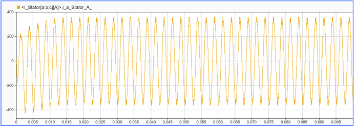
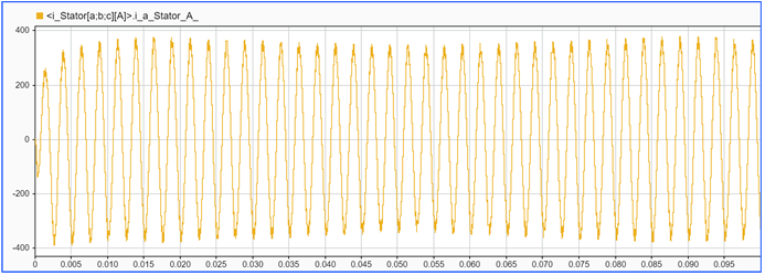
Emulation mode 1: controller through interrupt Trigger mode operation: motor current waveform (overall)
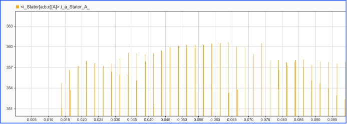
Emulation mode 1: The controller operates by interrupt triggering: motor current waveform (peak value)
Simulation mode 2: The controller operates by non-interrupt trigger mode: motor current waveform (overall)
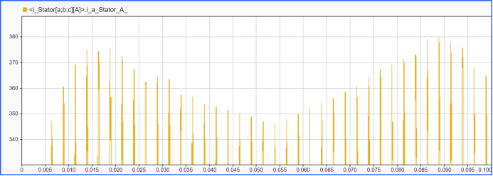
Simulation Mode 2: Controller runs with non-interrupt trigger: Motor current Waveform (peak value)
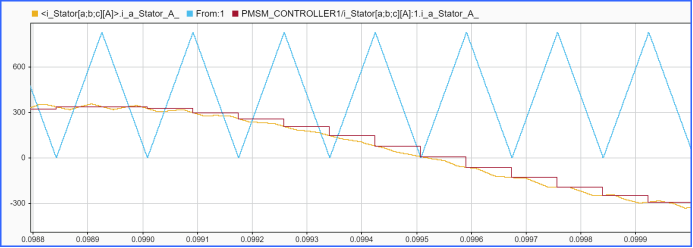
Simulation mode 1: The controller operates by interrupt triggering: motor current waveform, motor current sampling waveform, triangle wave
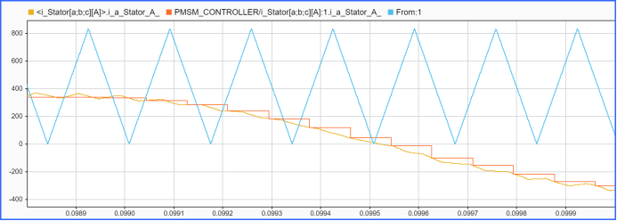
Simulation mode 2: The controller operates through non-interrupted triggering: motor current waveform, motor current sampling waveform, triangle wave
The differences are as follows:
Using the interrupt trigger method to model and simulate, the peak value of the motor current has a fluctuation of about 3A (0.83%);
Using non-interrupt trigger method for modeling and simulation, the peak value of the motor current has a low-frequency fluctuation of 35A (9.72%);
Using interrupt trigger method for modeling and simulation, the sampling value of the motor current is within the range of the triangular wave Bottom point and apex;
Using non-interrupt trigger mode modeling and simulation, the sampling value of the motor current has nothing to do with the bottom point and apex of the triangular wave;
How do you observe The waveform of the motor torque can see more obvious low-frequency fluctuations.