-
Mail us
sale@tiger-transformer.com -
Phone us
(+86)15155183777 -


Mail us
sale@tiger-transformer.comPhone us
(+86)15155183777
4 Charge Pump
A charge pump, also known as a switched capacitor voltage converter, is a device that utilizes so-called "flying" or "pumping" capacitors (and DC-DC (converter) that stores energy without an inductor or transformer.
4.1 Working Principle of Charge Pump
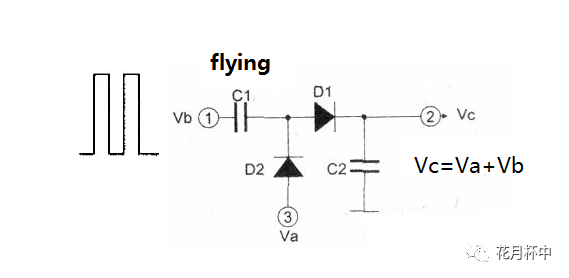
First of all, we briefly explain the basic working principle of charge pump, which is the principle of bootstrap circuit.
Suppose D1 and D2 are ideal diodes.
1) When Vb outputs 0V, Va charges the C1 and C2 capacitors, and the final voltage of C1 and C2 is Va;
2) When Vb outputs Vb, the C1 voltage suddenly changes to Va+ Vb. At this time, C2 is Va, which is less than the voltage of C1. C1 charges C2, and the final voltage of C1 and C2 is Va+△V1;
3) Vb output is 0V again, and the voltage of C1 suddenly changes to Va+△V1-Vb. Va charges the C1 capacitor, and finally C1 is Va, and C2 is Va+△V1;
4) When Vb outputs Vb again, the C1 voltage suddenly changes to Va+Vb. At this time, C2 is Va+△V1, which is less than the voltage of C1. C1 charges C2, and the final voltage of C1 and C2 is Va+△V1+△V2;
5) By analogy, after several cycles, Vc=Va+Vb.
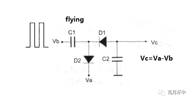
Similarly, if you want to obtain a lower negative pressure, what should you do?
The principle is the same. Va is a negative voltage, then adjust the diode direction as follows, and finally Vc=Va-Vb. .
Understand the working principle of the charge pump. According to the classification of power conversion, we will briefly talk about three types of charge pumps.
1) Voltage doubler charge pump.
2) Stabilized charge pump.
3) Inverse charge pump.
4.2 Voltage-doubling charge pump
The most common voltage-doubling charge pump is the double-voltage charge pump.
The double voltage charge pump boost circuit is shown below:
The working principle of the double voltage charge pump boost is the same as that of the bootstrap circuit. It's just that 4 transistors are used instead of diodes.
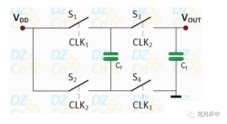
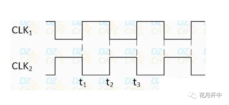
1) VDD is the input power supply, CF is the flying capacitor, and CL is the energy storage capacitor. The switches S1 to S4 can be composed of field effect transistors. They are controlled by two complementary clock signals CLK1 and CLK2. As shown below.
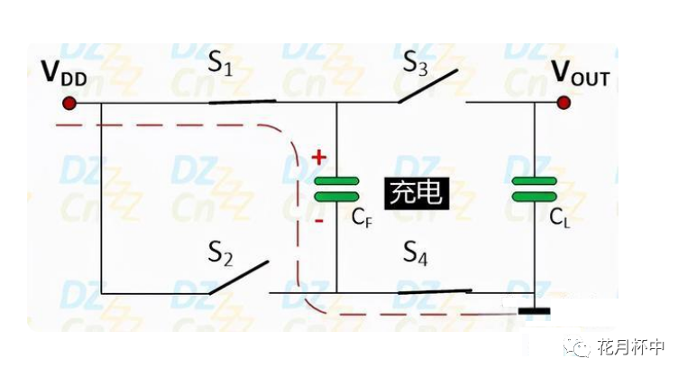
2) During the charging stage, switch S1/S4 is closed (on), S2/S3 is on (off). The flying capacitor CF is charged to the input voltage VDD and stores energy, which will be transferred in the next discharge stage. The energy storage capacitor CL has been charged to the 2VDD voltage by the energy transferred from CF in the previous discharge cycle, and provides load current.
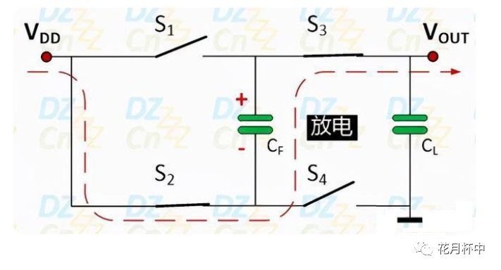
3) During the discharge phase, switch S1/S4 is open , S2/S3 is closed. The total voltage across CF is now 2VDD (hence the name of the double voltage charge pump). Then, CF discharge transfers the energy stored during the charging phase to CL and supplies the load current.
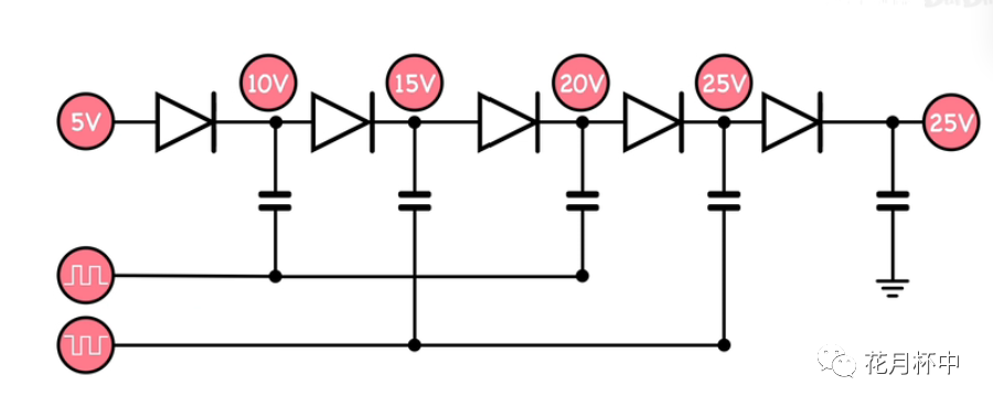
If we want to use a charge pump to obtain more multiples How to do the voltage?
Just use the bootstrap circuit nesting doll, as shown in the figure below.
4.3 Regulated charge pump
< p>The voltage-stabilizing charge pump is equivalent to the voltage-doubling charge pump + adjustment circuit.
Our power bank generally uses a voltage-stabilized charge pump. Students can think about why?
Generally, there are two types: voltage doubling charge pump + switch adjustment and voltage doubling charge pump + LDO.
4.3.1 Switch-adjusted voltage-stabilized charge pump
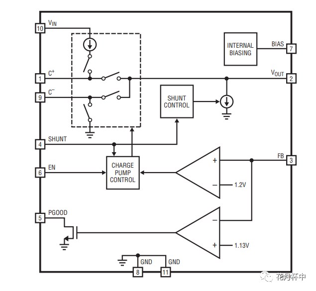
The working principle of the switch-adjusted voltage-stabilized charge pump is the same as the Buck type DC/DC type. When Vout<set voltage, it enters the charging stage. When Vout>set voltage, it enters the discharge stage. The figure below shows a typical switch-regulated voltage-regulated charge pump block diagram.
4.3.1 LDO regulated charge pump
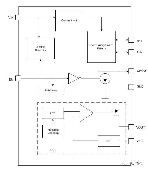
The working principle of the LDO voltage-stabilized charge pump is to double the voltage of the power supply and then stabilize the output voltage through the LDO. The figure below is a typical LDO regulated charge pump block diagram.
4.4 Inverse Charge Pump
The function of the reverse charge pump is to convert the positive power supply to the negative power supply or the negative power supply to the positive power supply.
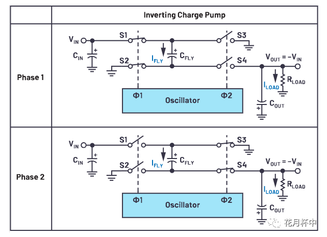
After mastering the voltage doubler charge pump, it is easy to look at the reverse charge pump. It is equivalent to adjusting the grounding position of the switch. The working principle is as follows:
1) During the charging phase, switches S1/S2 are closed (on), and S3/S4 are open (off). The flying capacitor CF is charged to the input voltage Vin.
2) During the discharge stage, switches S1/S2 are open (off), and S4/S4 are closed (on). The voltage of flying capacitor CF flips to -Vin and discharges to energy storage capacitor CL. Vout=-Vin.
Students can think about how to get reverse Voltage doubling charge pump and reverse regulated charge pump?
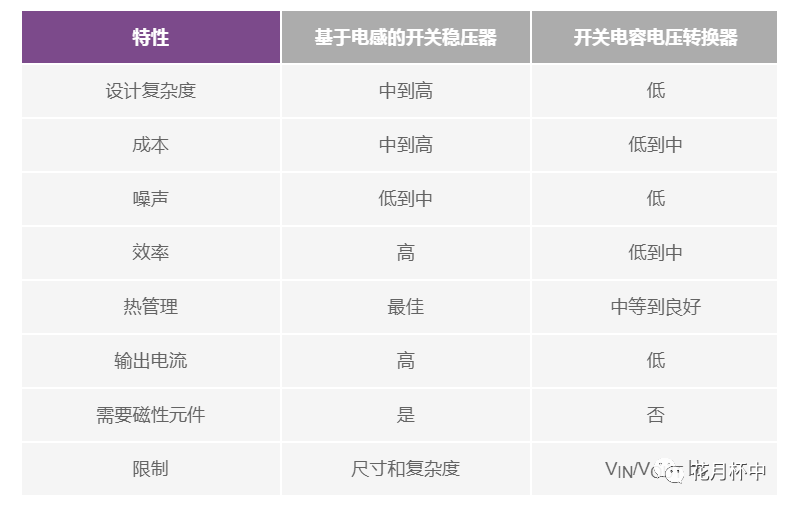
4.5 Advantages and disadvantages of charge pumps
1) Cost
The control circuit of the charge pump is simple, and the cost of capacitors is lower than that of inductors, so the design complexity and cost Both charge pumps have advantages.
2) Efficiency
The efficiency of the non-regulated charge pump is generally higher than that of the inductive switching regulator;
The efficiency of the regulated charge pump is lower than inductive switching regulators.
3) Noise
The noise of the non-regulated charge pump is generally higher than that of the inductive switching regulator;
The noise of the regulated charge pump is lower than inductive switching regulators.
4) Area and EMI
The charge pump does not use an inductor, and the capacitor area is smaller than the inductor, so it has advantages in EMI and area.
5) Output current
The charge pump energy storage device is a capacitor and has no freewheeling, so the output current is low.